Products
Chip Termination
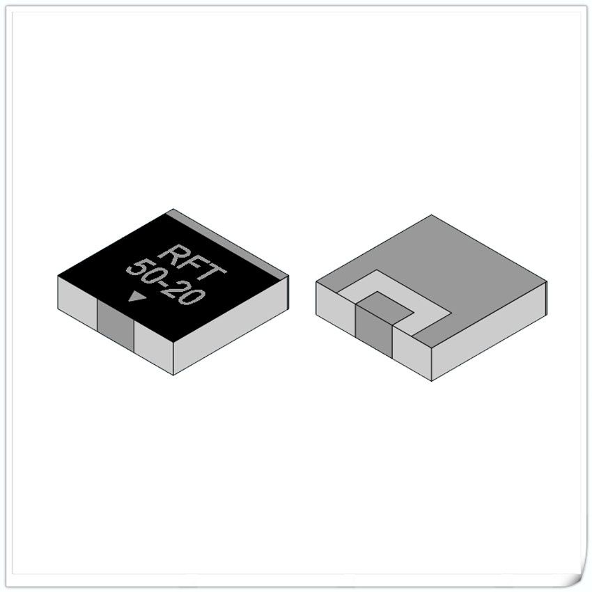
Chip Termination (Type A)
Chip Termination
Main technical specs:
Rated Power:10-500W;
Substrate materials:BeO、AlN、Al2O3
Nominal resistance value:50Ω
Resistance tolerance:±5%、±2%、±1%
emperature coefficient:<150ppm/℃
Operation temperature:-55~+150℃
ROHS standard: Compliant with
Applicable standard: Q/RFTYTR001-2022

| Power (W) | Frequency | Dimensions (unit: mm) | Substrate Material | Configuration | Data Sheet(PDF) | ||||||
| A | B | C | D | E | F | G | |||||
| 10W | 6GHz | 2.5 | 5.0 | 0.7 | 2.4 | / | 1.0 | 2.0 | AlN | FIG 2 | RFT50N-10CT2550 |
| 10GHz | 4.0 | 4.0 | 1.0 | 1.27 | 2.6 | 0.76 | 1.40 | BeO | FIG 1 | RFT50-10CT0404 | |
| 12W | 12GHz | 1.5 | 3 | 0.38 | 1.4 | / | 0.46 | 1.22 | AlN | FIG 2 | RFT50N-12CT1530 |
| 20W | 6GHz | 2.5 | 5.0 | 0.7 | 2.4 | / | 1.0 | 2.0 | AlN | FIG 2 | RFT50N-20CT2550 |
| 10GHz | 4.0 | 4.0 | 1.0 | 1.27 | 2.6 | 0.76 | 1.40 | BeO | FIG 1 | RFT50-20CT0404 | |
| 30W | 6GHz | 6.0 | 6.0 | 1.0 | 1.3 | 3.3 | 0.76 | 1.8 | AlN | FIG 1 | RFT50N-30CT0606 |
| 60W | 6GHz | 6.0 | 6.0 | 1.0 | 1.3 | 3.3 | 0.76 | 1.8 | AlN | FIG 1 | RFT50N-60CT0606 |
| 100W | 5GHz | 6.35 | 6.35 | 1.0 | 1.3 | 3.3 | 0.76 | 1.8 | BeO | FIG 1 | RFT50-100CT6363 |
Chip Termination (Type B)
Chip Termination
Main technical specs:
Rated Power:10-500W;
Substrate materials:BeO、AlN
Nominal resistance value:50Ω
Resistance tolerance:±5%、±2%、±1%
emperature coefficient:<150ppm/℃
Operation temperature:-55~+150℃
ROHS standard: Compliant with
Applicable standard: Q/RFTYTR001-2022
Solder joint size: see specification sheet
(customizable according to customer requirements)

| Power (W) | Frequency | Dimensions (unit: mm) | Substrate Material | Data Sheet(PDF) | ||||
| A | B | C | D | H | ||||
| 10W | 6GHz | 4.0 | 4.0 | 1.1 | 0.9 | 1.0 | AlN | RFT50N-10WT0404 |
| 8GHz | 4.0 | 4.0 | 1.1 | 0.9 | 1.0 | BeO | RFT50-10WT0404 | |
| 10GHz | 5.0 | 2.5 | 1.1 | 0.6 | 1.0 | BeO | RFT50-10WT5025 | |
| 20W | 6GHz | 4.0 | 4.0 | 1.1 | 0.9 | 1.0 | AlN | RFT50N-20WT0404 |
| 8GHz | 4.0 | 4.0 | 1.1 | 0.9 | 1.0 | BeO | RFT50-20WT0404 | |
| 10GHz | 5.0 | 2.5 | 1.1 | 0.6 | 1.0 | BeO | RFT50-20WT5025 | |
| 30W | 6GHz | 6.0 | 6.0 | 1.1 | 1.1 | 1.0 | AlN | RFT50N-30WT0606 |
| 60W | 6GHz | 6.0 | 6.0 | 1.1 | 1.1 | 1.0 | AlN | RFT50N-60WT0606 |
| 100W | 3GHz | 8.9 | 5.7 | 1.8 | 1.2 | 1.0 | AlN | RFT50N-100WT8957 |
| 6GHz | 8.9 | 5.7 | 1.8 | 1.2 | 1.0 | AlN | RFT50N-100WT8957B | |
| 8GHz | 9.0 | 6.0 | 1.4 | 1.1 | 1.5 | BeO | RFT50N-100WT0906C | |
| 150W | 3GHz | 6.35 | 9.5 | 2.0 | 1.1 | 1.0 | AlN | RFT50N-150WT6395 |
| 9.5 | 9.5 | 2.4 | 1.5 | 1.0 | BeO | RFT50-150WT9595 | ||
| 4GHz | 10.0 | 10.0 | 2.6 | 1.7 | 1.5 | BeO | RFT50-150WT1010 | |
| 6GHz | 10.0 | 10.0 | 2.6 | 1.7 | 1.5 | BeO | RFT50-150WT1010B | |
| 200W | 3GHz | 9.55 | 5.7 | 2.4 | 1.0 | 1.0 | AlN | RFT50N-200WT9557 |
| 9.5 | 9.5 | 2.4 | 1.5 | 1.0 | BeO | RFT50-200WT9595 | ||
| 4GHz | 10.0 | 10.0 | 2.6 | 1.7 | 1.5 | BeO | RFT50-200WT1010 | |
| 10GHz | 12.7 | 12.7 | 2.5 | 1.7 | 2.0 | BeO | RFT50-200WT1313B | |
| 250W | 3GHz | 12.0 | 10.0 | 1.5 | 1.5 | 1.5 | BeO | RFT50-250WT1210 |
| 10GHz | 12.7 | 12.7 | 2.5 | 1.7 | 2.0 | BeO | RFT50-250WT1313B | |
| 300W | 3GHz | 12.0 | 10.0 | 1.5 | 1.5 | 1.5 | BeO | RFT50-300WT1210 |
| 10GHz | 12.7 | 12.7 | 2.5 | 1.7 | 2.0 | BeO | RFT50-300WT1313B | |
| 400W | 2GHz | 12.7 | 12.7 | 2.5 | 1.7 | 2.0 | BeO | RFT50-400WT1313 |
| 500W | 2GHz | 12.7 | 12.7 | 2.5 | 1.7 | 2.0 | BeO | RFT50-500WT1313 |
Overview
Chip terminal resistors require selecting appropriate sizes and substrate materials based on different power and frequency requirements. The substrate materials are generally made of beryllium oxide, aluminum nitride, and aluminum oxide through resistance and circuit printing.
Chip terminal resistors can be divided into thin films or thick films, with various standard sizes and power options. We can also contact us for customized solutions according to customer requirements.
Surface mount technology (SMT) is a common form of electronic component packaging, commonly used for surface mount of circuit boards. Chip resistors are one type of resistor used to limit current, regulate circuit impedance, and local voltage.
Unlike traditional socket resistors, patch terminal resistors do not need to be connected to the circuit board through sockets, but are directly soldered to the surface of the circuit board. This packaging form helps to improve the compactness, performance, and reliability of circuit boards.
Chip terminal resistors require selecting appropriate sizes and substrate materials based on different power and frequency requirements. The substrate materials are generally made of beryllium oxide, aluminum nitride, and aluminum oxide through resistance and circuit printing.
Chip terminal resistors can be divided into thin films or thick films, with various standard sizes and power options. We can also contact us for customized solutions according to customer requirements.
Our company adopts the international general software HFSS for professional design and simulation development. Specialized power performance experiments were conducted to ensure power reliability. High precision network analyzers were used to test and screen its performance indicators, resulting in reliable performance.
Our company has developed and designed surface mount terminal resistors with different sizes, different powers (such as 2W-800W terminal resistors with different powers), and different frequencies (such as 1G-18GHz terminal resistors). Welcome customers to choose and use according to specific usage requirements.
Surface mount lead-free terminal resistors, also known as surface mount lead-free resistors, are a miniaturized electronic component. Its characteristic is that it does not have traditional leads, but is directly soldered onto the circuit board through SMT technology.
This type of resistor typically has the advantages of small size and light weight, enabling high-density circuit board design, saving space, and improving overall system integration. Due to the lack of leads, they also have lower parasitic inductance and capacitance, which is crucial for high-frequency applications, reducing signal interference and improving circuit performance.
The installation process of SMT lead-free terminal resistors is relatively simple, and batch installation can be carried out through automated equipment to improve production efficiency. Its heat dissipation performance is good, which can effectively reduce the heat generated by the resistor during operation and improve reliability.
In addition, this type of resistor has high accuracy and can meet various application requirements with strict resistance values. They are widely used in electronic products, such as passive components RF isolators. Couplers, coaxial loads, and other fields.
Overall, SMT lead-free terminal resistors have become an indispensable part of modern electronic design due to their small size, good high-frequency performance, and easy installation


