
Products


Coaxial Low PIM Termination
Data Sheet
| RFTYT DC-6GHz Low PIM Termination | |||||||||
| Power | Connector Type | Freq.Range | Impedance (Ω) |
VSWR max |
PIM (dBc@2*43dBm) |
Waterproof Grade | Dimension size (mm) |
Data Sheet M Type | Data Sheet F Type |
| 10W | N | DC-3G | 50 | 1.20 | ≥140dBc@2*33dBm | IP65 | Φ35.0*40.0 | CT10W-RX3540-IP65-NJ-3G | CT10W-RX3540-IP65-NK-3G |
| DIN | DC-3G | 50 | 1.20 | ≥140dBc@2*33dBm | IP65 | Φ35.0*40.0 | CT10W-RX3540-IP65-DINJ-3G | CT10W-RX3540-IP65-DINK-3G | |
| 5-50W | N | 0.35-4G | 50 | 1.25 | ≤-150/-155/-160 | IP65 or IP67 | Φ50.0*150.0 | CT30W-RX5015-IP65-NJ/0.35-4G | CT30W-RX5015-IP65-NK/0.35-4G |
| 0.35-6G | 50 | 1.30 | ≤-150/-155/-160 | IP65 or IP67 | Φ50.0*150.0 | CT30W-RX5015-IP65-NJ/0.35-6G | CT30W-RX5015-IP65-NK/0.35-6G | ||
| 4.3-10 | 0.35-4G | 50 | 1.25 | ≤-150/-155/-160 | IP65 or IP67 | Φ50.0*150.0 | CT30W-RX5015-IP65-4310J/0.35-4G | CT30W-RX5015-IP65-4310K/0.35-4G | |
| 0.35-6G | 50 | 1.30 | ≤-150/-155/-160 | IP65 or IP67 | Φ50.0*150.0 | CT30W-RX5015-IP65-4310J/0.35-6G | CT30W-RX5015-IP65-4310K/0.35-6G | ||
| DIN | 0.35-4G | 50 | 1.25 | ≤-150/-155/-160 | IP65 or IP67 | Φ50.0*150.0 | CT30W-RX5015-IP65-DINJ/0.35-4G | CT30W-RX5015-IP65-DINK/0.35-4G | |
| 0.35-6G | 50 | 1.30 | ≤-150/-155/-160 | IP65 or IP67 | Φ50.0*150.0 | CT30W-RX5015-IP65-DINJ/0.35-6G | CT30W-RX5015-IP65-DINK/0.35-6G | ||
| 50W | N | DC-3G | 50 | 1.20 | ≤-120 | IP65 or IP67 | 60.0*60.0*80.0 | CT50W-FH6080-IP65-NJ-3G | CT50W-FH6080-IP65-NK-3G |
| DIN | DC-3G | 50 | 1.20 | ≤-120 | IP65 or IP67 | 60.0*60.0*80.0 | CT50W-FH6080-IP65-DINJ-3G | / | |
| 100W | N | 0.35-4G | 50 | 1.25 | ≤-150/-155/-160 | IP65 or IP67 | Φ83.0*150.0 | CT100W-RX8315-IP65-NJ/0.35-4G | CT100W-RX8315-IP65-NK/0.35-4G |
| 0.35-6G | 50 | 1.30 | ≤-150/-155/-160 | IP65 or IP67 | Φ83.0*150.0 | CT100W-RX8315-IP65-NJ/0.35-6G | CT100W-RX8315-IP65-NK/0.35-6G | ||
| 4.3-10 | 0.35-4G | 50 | 1.25 | ≤-150/-155/-160 | IP65 or IP67 | Φ83.0*150.0 | CT100W-RX8315-IP65-4310J/0.35-4G | CT100W-RX8315-IP65-4310K/0.35-4G | |
| 0.35-6G | 50 | 1.30 | ≤-150/-155/-160 | IP65 or IP67 | Φ83.0*150.0 | CT100W-RX8315-IP65-4310J/0.35-6G | CT100W-RX8315-IP65-4310K/0.35-6G | ||
| DIN | 0.35-4G | 50 | 1.25 | ≤-150/-155/-160 | IP65 or IP67 | Φ83.0*150.0 | CT100W-RX8315-IP65-DINJ/0.35-4G | CT100W-RX8315-IP65-DINK/0.35-4G | |
| 0.35-6G | 50 | 1.30 | ≤-150/-155/-160 | IP65 or IP67 | Φ83.0*150.0 | CT100W-RX8315-IP65-DINJ/0.35-6G | CT100W-RX8315-IP65-DINK/0.35-6G | ||
| 200W | N | 0.35-4G | 50 | 1.25 | ≤-150/-155/-160 | IP65 or IP67 | Φ83.0*150.0 | CT200W-RX1720-IP65-NJ/0.35-4G | CT200W-RX1720-IP65-NK/0.35-4G |
| 0.35-6G | 50 | 1.30 | ≤-150/-155/-160 | IP65 or IP67 | Φ83.0*150.0 | CT200W-RX1720-IP65-NJ/0.35-6G | CT200W-RX1720-IP65-NK/0.35-6G | ||
| 4.3-10 | 0.35-4G | 50 | 1.25 | ≤-150/-155/-160 | IP65 or IP67 | Φ83.0*150.0 | CT200W-RX1720-IP65-4310J/0.35-4G | CT200W-RX1720-IP65-4310K/0.35-4G | |
| 0.35-6G | 50 | 1.30 | ≤-150/-155/-160 | IP65 or IP67 | Φ83.0*150.0 | CT200W-RX1720-IP65-4310J/0.35-6G | CT200W-RX1720-IP65-4310K/0.35-6G | ||
| DIN | 0.35-4G | 50 | 1.25 | ≤-150/-155/-160 | IP65 or IP67 | Φ83.0*150.0 | CT200W-RX1720-IP65-DINJ/0.35-4G | CT200W-RX1720-IP65-DINK/0.35-4G | |
| 0.35-6G | 50 | 1.30 | ≤-150/-155/-160 | IP65 or IP67 | Φ83.0*150.0 | CT200W-RX1720-IP65-DINJ/0.35-6G | CT200W-RX1720-IP65-DINK/0.35-6G | ||
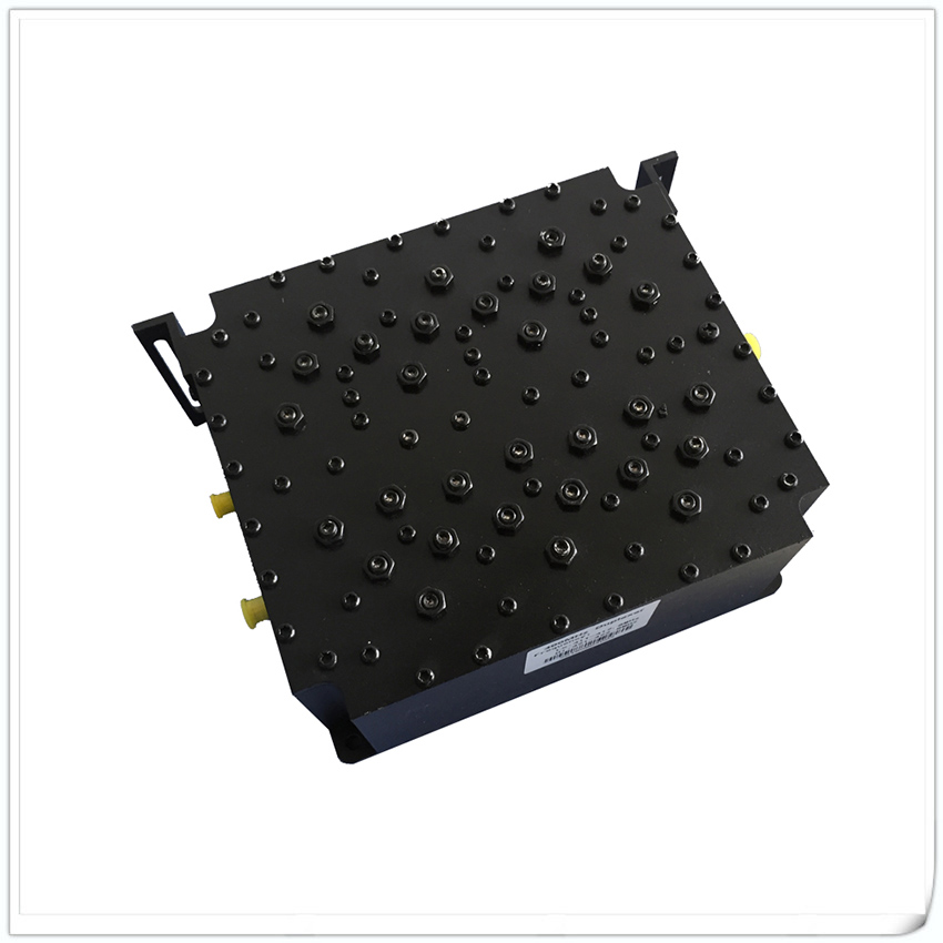
Overview
The coaxial load is assembled by connectors, heat sinks, and built-in resistor chips. According to different frequencies and powers, connectors typically use types such as 2.92, SMA, N, DIN, 4.3-10, etc. The heat sink is designed with corresponding heat dissipation dimensions according to the heat dissipation requirements of different power sizes. The built-in chip adopts a single chip or multiple chipsets according to different frequency and power requirements.
Its main purpose is to absorb the power of radio frequency or microwave systems; Or as a dummy load for antennas and transmitter terminals. In some RF tests, in order to avoid signal reflection and affect the test results, it is connected to unused ports as matching loads to absorb port energy. It can also serve as a dummy load in evaluating system performance through simulated terminals (such as antennas).
The coaxial load series products have the characteristics of wide working frequency band, low standing wave coefficient, high power, small size, and not easy to burn.