
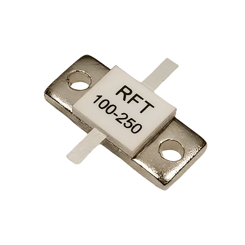
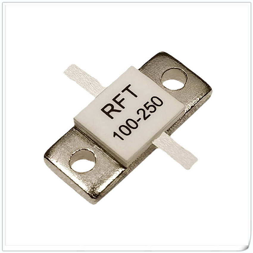
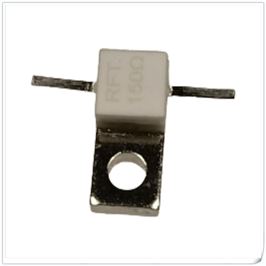
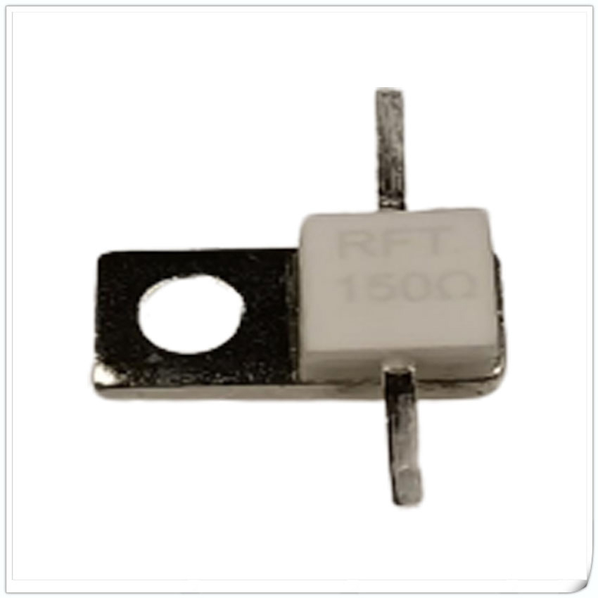
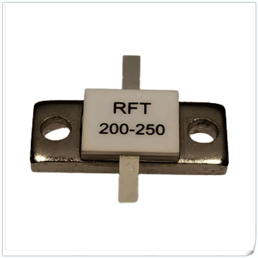
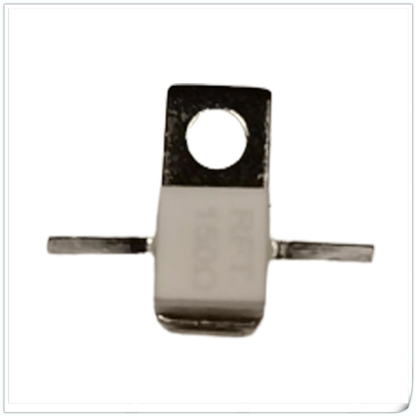
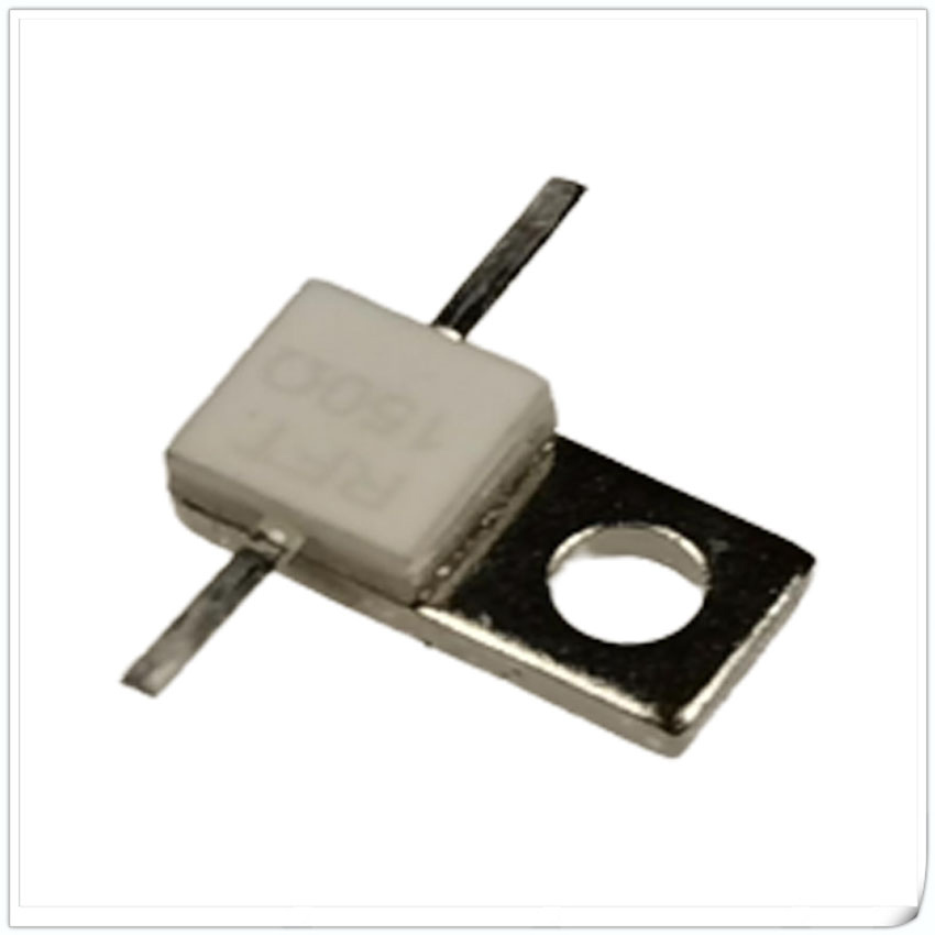
Flanged Resistor

Data Sheet
Flanged Resistor
Rated power: 10-800W;
Substrate materials: BeO, AlN, Al2O3
Nominal resistance value: 100 Ω (10-3000 Ω optional)
Resistance tolerance: ± 5%, ± 2%, ± 1%
Temperature coefficient: < 150ppm/℃
Operation temperature: -55~+150 ℃
Flange coating: optional nickel or silver plating
ROHS standard: Compliant with
Applicable standard: Q/RFTYTR001-2022
Lead length: L as specified in the specification sheet (can be customized according to customer requirements)

Data Sheet
| Power W |
capacitance PF@100Ω |
Dimension(unit:mm) | Substrate Material | Configuration | Data Sheet(PDF) | ||||||||||
| A | B | C | D | E | H | G | W | L | J | Φ | |||||
| 10 | 2.4 | 7.7 | 5.0 | 5.1 | 2.5 | 1.5 | 2.5 | 3.5 | 1.0 | 4.0 | / | 3.1 | AlN | FIG2 | RFTXXN-10RM7750 |
| 10 | 1.2 | 7.7 | 5.0 | 5.1 | 2.5 | 1.5 | 2.5 | 3.5 | 1.0 | 4.0 | / | 3.1 | BeO | FIG2 | RFTXX-10RM7750 |
| Power W |
capacitance PF@100Ω |
Dimension(unit:mm) | Substrate Material | Configuration | Data Sheet(PDF) | ||||||||||
| A | B | C | D | E | H | G | W | L | J | Φ | |||||
| 20 | 2.3 | 9.0 | 4.0 | 7.0 | 4.0 | 0.8 | 1.8 | 2.6 | 1.0 | 4.0 | / | 2.0 | AlN | FIG2 | RFTXXN-20RM0904 |
| 20 | 1.2 | 9.0 | 4.0 | 7.0 | 4.0 | 0.8 | 1.8 | 2.6 | 1.0 | 4.0 | / | 2.0 | BeO | FIG2 | RFTXX-20RM0904 |
| 20 | 2.3 | 11.0 | 4.0 | 7.6 | 4.0 | 0.8 | 1.8 | 2.6 | 1.0 | 3.0 | / | 2.0 | AlN | FIG1 | RFTXXN-20RM1104 |
| 20 | 1.2 | 11.0 | 4.0 | 7.6 | 4.0 | 0.8 | 1.8 | 2.6 | 1.0 | 3.0 | / | 2.0 | BeO | FIG1 | RFTXX-20RM1104 |
| 20 | 2.3 | 13.0 | 4.0 | 9.0 | 4.0 | 0.8 | 1.8 | 2.6 | 1.0 | 4.0 | / | 2.0 | AlN | FIG1 | RFTXXN-20RM1304 |
| 20 | 1.2 | 13.0 | 4.0 | 9.0 | 4.0 | 0.8 | 1.8 | 2.6 | 1.0 | 4.0 | / | 2.0 | BeO | FIG1 | RFTXX-20RM1304 |
| Power W |
capacitance PF@100Ω |
Dimension(unit:mm) | Substrate Material | Configuration | Data Sheet(PDF) | ||||||||||
| A | B | C | D | E | H | G | W | L | J | Φ | |||||
| 30 | 1.2 | 9.0 | 4.0 | 7.0 | 4.0 | 0.8 | 1.8 | 2.6 | 1.0 | 4.0 | / | 2.0 | BeO | FIG2 | RFTXX-30RM0904 |
| 30 | 1.2 | 13.0 | 4.0 | 9.0 | 4.0 | 0.8 | 1.8 | 2.6 | 1.0 | 4.0 | / | 2.0 | BeO | FIG1 | RFTXX-30RM1304 |
| 30 | 2.9 | 13.0 | 6.0 | 10.0 | 6.0 | 1.5 | 2.5 | 3.3 | 1.0 | 5.0 | / | 3.2 | AlN | FIG2 | RFTXXN-30RM1306 |
| 30 | 2.6 | 13.0 | 6.0 | 10.0 | 6.0 | 1.5 | 2.5 | 3.3 | 1.0 | 5.0 | / | 3.2 | BeO | FIG2 | RFTXX-30RM1306 |
| 30 | 1.2 | 13.0 | 6.0 | 10.0 | 6.0 | 1.5 | 5.0 | 5.9 | 1.0 | 5.0 | / | 3.2 | BeO | FIG2 | RFTXX-30RM1306F |
| 30 | 2.9 | 20.0 | 6.0 | 14.0 | 6.0 | 1.5 | 2.5 | 3.3 | 1.0 | 5.0 | / | 3.2 | AlN | FIG1 | RFTXXN-30RM2006 |
| 30 | 2.6 | 20.0 | 6.0 | 14.0 | 6.0 | 1.5 | 2.5 | 3.3 | 1.0 | 5.0 | / | 3.2 | BeO | FIG1 | RFTXX-30RM2006 |
| 30 | 1.2 | 20.0 | 6.0 | 14.0 | 6.0 | 1.5 | 5.0 | 5.9 | 1.0 | 5.0 | / | 3.2 | BeO | FIG1 | RFTXX-30RM2006F |
| Power W |
capacitance PF@100Ω |
Dimension(unit:mm) | Substrate Material | Configuration | Data Sheet(PDF) | ||||||||||
| A | B | C | D | E | H | G | W | L | J | Φ | |||||
| 60W | 2.9 | 13.0 | 6.0 | 10.0 | 6.0 | 1.5 | 2.5 | 3.3 | 1.0 | 5.0 | / | 3.2 | AlN | FIG2 | RFTXXN-60RM1306 |
| 60W | 2.6 | 13.0 | 6.0 | 10.0 | 6.0 | 1.5 | 2.5 | 3.3 | 1.0 | 5.0 | / | 3.2 | BeO | FIG2 | RFTXX-60RM1306 |
| 60W | 1.2 | 13.0 | 6.0 | 10.0 | 6.0 | 1.5 | 5.0 | 5.9 | 1.0 | 5.0 | / | 3.2 | BeO | FIG2 | RFTXX-60RM1306F |
| 60W | 2.9 | 20.0 | 6.0 | 14.0 | 6.0 | 1.5 | 2.5 | 3.3 | 1.0 | 5.0 | / | 3.2 | AlN | FIG1 | RFTXXN-60RM2006 |
| 60W | 2.6 | 20.0 | 6.0 | 14.0 | 6.0 | 1.5 | 2.5 | 3.3 | 1.0 | 5.0 | / | 3.2 | BeO | FIG1 | RFTXX-60RM2006 |
| 60W | 1.2 | 20.0 | 6.0 | 14.0 | 6.0 | 1.5 | 5.0 | 5.9 | 1.0 | 5.0 | / | 3.2 | BeO | FIG1 | RFTXX-60RM2006F |
| Power W |
capacitance PF@100Ω |
Dimension(unit:mm) | Substrate Material | Configuration | Data Sheet(PDF) | ||||||||||
| A | B | C | D | E | H | G | W | L | J | Φ | |||||
| 100 | 2.6 | 16.0 | 6.0 | 10.0 | 6.0 | 1.5 | 2.5 | 3.3 | 1.0 | 5.0 | / | 3.2 | BeO | FIG2 | RFTXX-100RM1306 |
| 100 | 2.1 | 20.0 | 6.0 | 14.0 | 8.9 | 1.5 | 3.0 | 3.5 | 1.0 | 5.0 | / | 3.2 | AlN | FIG1 | RFTXXN-100RJ2006B |
| 100 | 2.1 | 16.0 | 6.0 | 13.0 | 8.9 | 1.0 | 2.5 | 3.0 | 1.0 | 5.0 | / | 2.1 | AlN | FIG1 | RFTXXN-100RJ1606B |
| 100 | 3.9 | 22.0 | 9.5 | 14.2 | 6.35 | 1.5 | 2.5 | 3.3 | 1.4 | 6.0 | / | 4.0 | BeO | FIG1 | RFTXX-100RM2295 |
| 100 | 5.6 | 16.0 | 10.0 | 13.0 | 10.0 | 1.5 | 2.5 | 3.3 | 2.4 | 6.0 | / | 3.2 | BeO | FIG4 | RFTXX-100RM1610 |
| 100 | 5.6 | 23.0 | 10.0 | 17.0 | 10.0 | 1.5 | 2.5 | 3.3 | 2.4 | 6.0 | / | 3.2 | BeO | FIG3 | RFTXX-100RM2310 |
| 100 | 5.6 | 24.8 | 10.0 | 18.4 | 10.0 | 3.0 | 4.0 | 5.0 | 2.4 | 6.0 | / | 3.5 | BeO | FIG1 | RFTXX-100RM2510 |
| 100 | 4.0 | 24.8 | 10.0 | 18.4 | 10.0 | 3.0 | 4.5 | 5.3 | 2.4 | 6.0 | / | 3.5 | BeO | FIG1 | RFTXX-100RM2510B |

| Power W |
Capacitance PF@100Ω |
Dimensions(unit:mm) | Substrate Material |
Configuration | Data Sheet(PDF) | ||||||||||
| A | B | C | D | E | H | G | W | L | J | Φ | |||||
| 150W | 3.9 | 22.0 | 9.5 | 14.2 | 6.35 | 1.5 | 2.5 | 3.3 | 1.4 | 6.0 | / | 4.0 | BeO | FIG1 | RFTXX-150RM2295 |
| 150W | 5.6 | 16.0 | 10.0 | 13.0 | 10.0 | 1.5 | 2.5 | 3.3 | 2.4 | 6.0 | / | 3.2 | BeO | FIG4 | RFTXX-150RM1610 |
| 150W | 5.6 | 23.0 | 10.0 | 17.0 | 10.0 | 1.5 | 2.5 | 3.3 | 2.4 | 6.0 | / | 3.2 | BeO | FIG3 |
RFTXX-150RM2310 |
| 150W | 5.0 | 24.8 | 10.0 | 18.4 | 10.0 | 3.0 | 4.0 | 5.0 | 2.4 | 6.0 | / | 3.5 | BeO | FIG1 | RFTXX-150RM2510 |
| Power W |
Capacitance PF@100Ω |
Dimensions(unit:mm) | Substrate Material | Configuration | Data Sheet(PDF) | ||||||||||
| A | B | C | D | E | H | G | W | L | J | Φ | |||||
| 250 | 5.6 | 23.0 | 10.0 | 17.0 | 10.0 | 1.5 | 3.8 | 3.3 | 2.4 | 6.0 | / | 3.2 | BeO | FIG3 | RFTXX-250RM2310 |
| 250 | 5.6 | 24.8 | 10.0 | 18.4 | 12.0 | 3.0 | 4.0 | 4.8 | 2.4 | 6.0 | / | 3.5 | BeO | FIG1 | RFTXX-250RM2510 |
| 250 | 4.0 | 24.8 | 10.0 | 18.4 | 10.0 | 3.0 | 4.5 | 5.3 | 2.4 | 6.0 | / | 3.5 | BeO | FIG1 | RFTXX-250RM2510B |
| 250 | 5.0 | 27.0 | 10.0 | 21.0 | 10.0 | 2.5 | 3.5 | 4.3 | 2.4 | 6.0 | / | 3.2 | BeO | FIG1 | RFTXX-250RM2710 |
| Power W |
Capacitance PF@100Ω |
Dimensions(unit:mm) | Substrate Material | Configuration | Data Sheet(PDF) | ||||||||||
| A | B | C | D | E | H | G | W | L | J | Φ | |||||
| 300 | 5.0 | 24.8 | 10.0 | 18.4 | 12.0 | 3.0 | 4.0 | 4.8 | 2.4 | 6.0 | / | 3.5 | BeO | FIG1 |
RFTXX-300RM2510 |
| 300 | 4.0 | 24.8 | 10.0 | 18.4 | 10.0 | 3.0 | 4.5 | 5.3 | 2.4 | 6.0 | / | 3.5 | BeO | FIG1 |
RFTXX-300RM2510B |
| 300 | 5.6 | 27.0 | 10.0 | 21.0 | 10.0 | 2.5 | 3.5 | 4.3 | 2.4 | 6.0 | / | 3.2 | BeO | FIG1 | RFTXX-300RM2710 |
| 300 | 2.0 | 27.8 | 12.7 | 20.0 | 12.7 | 3.0 | 9.0 | 10.0 | 2.4 | 6.0 | / | 4.5 | BeO | FIG1 | RFTXX-300RM2813K |
| Power W |
Capacitance PF@100Ω |
Dimensions(unit:mm) | Substrate Material | Configuration | Data Sheet(PDF) | ||||||||||
| A | B | C | D | E | H | G | W | L | J | Φ | |||||
| 400 | 8.5 | 32.0 | 12.7 | 22.0 | 12.7 | 3.0 | 4.5 | 5.5 | 2.4 | 6.0 | / | 4.0 | BeO | FIG1 | RFTXX-400RM3213 |
| 400 | 2.0 | 32.0 | 12.7 | 22.0 | 12.7 | 3.0 | 9.0 | 10.0 | 2.4 | 6.0 | / | 4.0 | BeO | FIG1 | RFTXX-400RM3213K |
| 400 | 8.5 | 27.8 | 12.7 | 20.0 | 12.7 | 3.0 | 4.5 | 5.5 | 2.4 | 6.0 | / | 4.5 | BeO | FIG1 |
RFTXX-400RM2813 |
| 400 | 2.0 | 27.8 | 12.7 | 20.0 | 12.7 | 3.0 | 9.0 | 10.0 | 2.4 | 6.0 | / | 4.5 | BeO | FIG1 | RFTXX-400RM2813K |
| Power W |
Capacitance PF@100Ω |
Dimensions(unit:mm) | Substrate Material | Configuration | Data Sheet(PDF) | ||||||||||
| A | B | C | D | E | H | G | W | L | J | Φ | |||||
| 500 | 8.5 | 32.0 | 12.7 | 22.0 | 12.7 | 3.0 | 4.5 | 5.5 | 2.4 | 6.0 | / | 4.0 | BeO | FIG1 | RFTXX-500RM3213 |
| 500 | 2.0 | 32.0 | 12.7 | 22.0 | 12.7 | 3.0 | 9.0 | 10.0 | 2.4 | 6.0 | / | 4.0 | BeO | FIG1 | RFTXX-500RM3213K |
| 500 | 8.5 | 27.8 | 12.7 | 20.0 | 12.7 | 3.0 | 4.5 | 5.5 | 2.4 | 6.0 | / | 4.5 | BeO | FIG1 |
RFTXX-500RM2813 |
| 500 | 21.8 | 48.0 | 26.0 | 40.0 | 25.4 | 3.0 | 4.6 | 5.2 | 6.0 | 7.0 | 12.7 | 4.2 | BeO | FIG5 | RFTXX-500RM4826 |
| 600 | 21.8 | 48.0 | 26.0 | 40.0 | 25.4 | 3.0 | 4.6 | 5.2 | 6.0 | 7.0 | 12.7 | 4.2 | BeO | FIG5 | RFTXX-600RM4826 |
| 800 | 21.8 | 48.0 | 26.0 | 40.0 | 25.4 | 3.0 | 4.6 | 5.2 | 6.0 | 7.0 | 12.7 | 4.2 | BeO | FIG5 | RFTXX-800RM4826 |
Overview
Flanged resistors can be widely used in balanced amplifiers, balanced bridges, and communication systems.
The resistance value of the flanged resistor should be selected based on specific circuit requirements and signal characteristics.
In general, the resistance value should match the characteristic resistance value of the circuit to ensure its balance and stable operation.
The power of flange mount resistor should be selected based on the power demand of the circuit.
In general, the power of the resistor should be greater than the maximum power of the circuit to ensure its normal operation.
Flanged resistor is assembled by welding the flange and double lead resistor.
The flange is designed for installation in the circuit and can also provide better heat dissipation for resistors in use.
The flanged resistor is one of the commonly used passive components in electronic circuits, which has the function of balancing circuits.
It adjusts the resistance value in the circuit to achieve a balanced state of current or voltage, thereby achieving stable operation of the circuit.
It plays an important role in electronic devices and communication systems.
In a circuit, when the resistance value is unbalanced, the current or voltage will be unevenly distributed, leading to the instability of the circuit.
The flanged resistor can balance the distribution of current or voltage by adjusting the resistance in the circuit.
The flange balancing resistor adjusts the resistance value in the circuit to evenly distribute current or voltage across various branches, thereby achieving balanced operation of the circuit.
The flanged lead resistor can be widely used in balanced amplifiers, balanced bridges, and communication systems
The resistance value of the flange double lead should be selected based on specific circuit requirements and signal characteristics.
In general, the resistance value should match the characteristic resistance value of the circuit to ensure the balance and stable operation of the circuit.
The power of the flanged resistor should be selected according to the power requirements of the circuit.
In general, the power of the resistor should be greater than the maximum power of the circuit to ensure its normal operation.
The flanged resistor is assembled by welding the flange and double lead resistor.
The flange is designed for installation in circuits and can also provide better heat dissipation for resistors during use.
Our company can also customize flanges and resistors according to specific customer requirements.


