Passive Device for RF Circulator
1. The function of the RF circular device
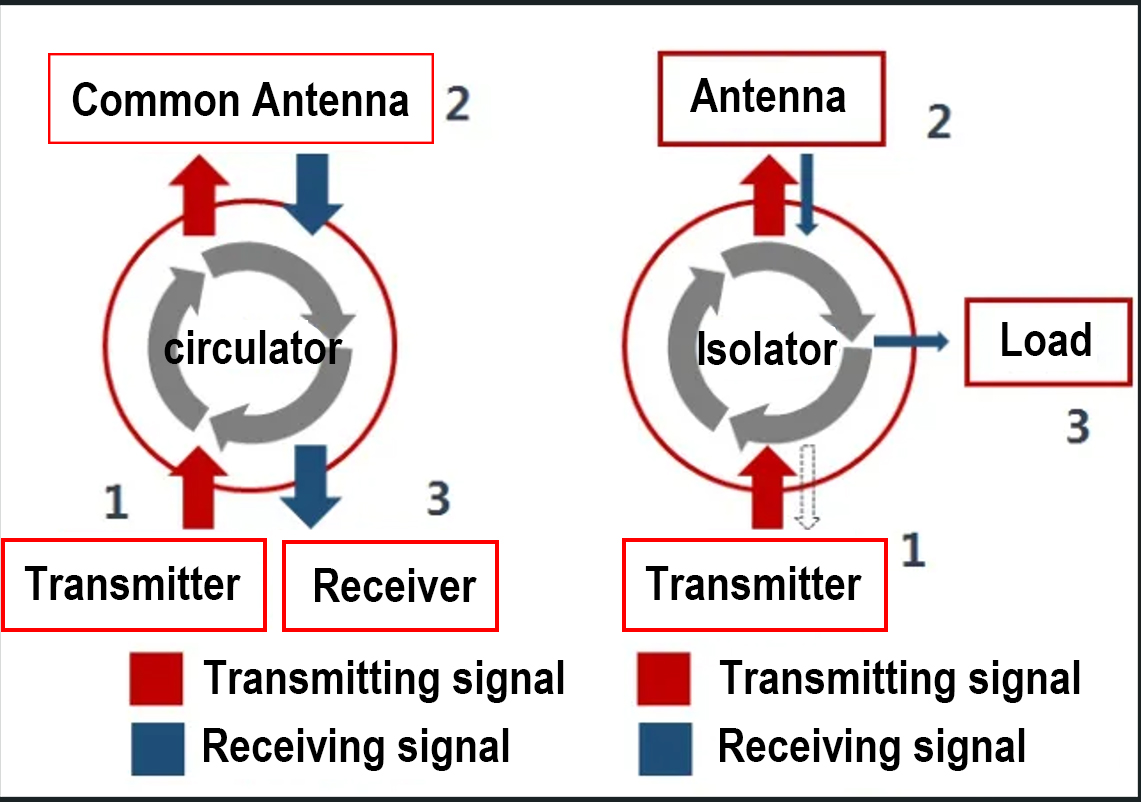
The RF circulator device is a three port device with unidirectional transmission characteristics, indicating that the device is conductive from 1 to 2, from 2 to 3, and from 3 to 1, while the signal is isolated from 2 to 1, from 3 to 2, and from 1 to 3. Changing the direction of the ferrite bias field can alter the direction of signal conduction, and a matching load can be used as an isolator at one end of the RF circulator.
RF Circulator play a role in directional signal transmission and duplex transmission in systems, and can be used in radar/communication systems to isolate the receiving/transmitting signals from each other. Transmission and reception can share the same antenna.
RF isolators play a important role in inter stage isolation, impedance matching, transmission of power signals, and protection of the front-end power synthesis system in the system. By using power load to withstand the reverse power signal caused by matching or possible fault mismatch in the later stage, the front-end power synthesis system is protected, which is an important component in communication systems.

2. The Structure of the RF Circulator
The principle of a RF Circulator device is to bias the anisotropic properties of ferrite materials with a magnetic field. By utilizing the Faraday rotation effect of the polarization plane rotating when electromagnetic waves are transmitted in a rotating ferrite material with an external DC magnetic field, and through appropriate design, the polarization plane of the electromagnetic wave is perpendicular to the grounded resistive plug during forward transmission, resulting in minimal attenuation. In reverse transmission, the polarization plane of the electromagnetic wave is parallel to the grounded resistive plug and is almost completely absorbed. Microwave structures include microstrip, waveguide, strip line, and coaxial types, among which microstrip three terminal circulators are the most commonly used. Ferrite materials are used as the medium, and a conduction band structure is placed on top, with a constant magnetic field added, to achieve circulator characteristics. If the direction of the bias magnetic field is changed, the direction of the loop will change.
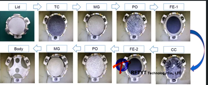
The following figure shows the structure of a surface mounted annular device, consisting of a central conductor (CC), ferrite (FE), uniform magnetic plate (PO), magnet (MG), temperature compensation plate (TC), lid (Lid), and body.

3. Common forms of RF Circulator
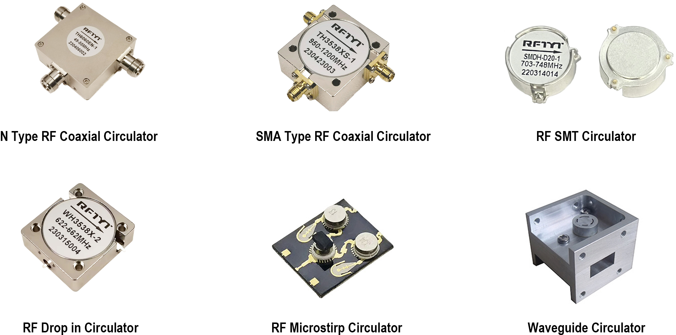
Including coaxial circulator (N, SMA), surface mount ring resonator (SMT circulator), strip line ciruclator (D, also known as drop in ciruclator), waveguide circulator(W), microstrip circulator (M, also known as substratecirculator), as shown in the figure.

4. Important indicators of RF Circulator
1.Frequency range
2.Transmission direction
Clockwise and anticlockwise, also known as left hoop and right hoop rotation.

3.Insertion loss
It describes the energy of a signal transmitted from one end to the other, and the smaller the insertion loss, the better.
4.Isolation
The greater the isolation, the better, and an absolute value greater than 20dB is preferable.
5.VSWR/Return loss
The closer the VSWR is to 1, the better, and the absolute value of the return loss is greater than 18dB.
6.Connector type
Generally, there are N, SMA, BNC,TAB etc
7.Power (forward power ,reverse power, peak power)
8.Operating Temperature
9.Dimension
The following figure shows the technical specifications of some RF Circulator by RFTYT
| RFTYT 30MHz-18.0GHz RF Coaxial Circulator | |||||||||
| Model | Freq.Range | BW Max. | IL.(dB) | Isolation (dB) | VSWR | Forward Power (W) | Dimension WxLxHmm | SMA Type | N Type |
| TH6466H | 30-40MHz | 5% | 2.00 | 18.0 | 1.30 | 100 | 60.0*60.0*25.5 | ||
| TH6060E | 40-400 MHz | 50% | 0.80 | 18.0 | 1.30 | 100 | 60.0*60.0*25.5 | ||
| TH5258E | 160-330 MHz | 20% | 0.40 | 20.0 | 1.25 | 500 | 52.0*57.5*22.0 | ||
| TH4550X | 250-1400 MHz | 40% | 0.30 | 23.0 | 1.20 | 400 | 45.0*50.0*25.0 | ||
| TH4149A | 300-1000MHz | 50% | 0.40 | 16.0 | 1.40 | 30 | 41.0*49.0*20.0 | / | |
| TH3538X | 300-1850 MHz | 30% | 0.30 | 23.0 | 1.20 | 300 | 35.0*38.0*15.0 | ||
| TH3033X | 700-3000 MHz | 25% | 0.30 | 23.0 | 1.20 | 300 | 32.0*32.0*15.0 | / | |
| TH3232X | 700-3000 MHz | 25% | 0.30 | 23.0 | 1.20 | 300 | 30.0*33.0*15.0 | / | |
| TH2528X | 700-5000 MHz | 25% | 0.30 | 23.0 | 1.20 | 200 | 25.4*28.5*15.0 | ||
| TH6466K | 950-2000 MHz | Full | 0.70 | 17.0 | 1.40 | 150 | 64.0*66.0*26.0 | ||
| TH2025X | 1300-6000 MHz | 20% | 0.25 | 25.0 | 1.15 | 150 | 20.0*25.4*15.0 | / | |
| TH5050A | 1.5-3.0 GHz | Full | 0.70 | 18.0 | 1.30 | 150 | 50.8*49.5*19.0 | ||
| TH4040A | 1.7-3.5 GHz | Full | 0.70 | 17.0 | 1.35 | 150 | 40.0*40.0*20.0 | ||
| TH3234A | 2.0-4.0 GHz | Full | 0.40 | 18.0 | 1.30 | 150 | 32.0*34.0*21.0 | ||
| TH3234B | 2.0-4.0 GHz | Full | 0.40 | 18.0 | 1.30 | 150 | 32.0*34.0*21.0 | ||
| TH3030B | 2.0-6.0 GHz | Full | 0.85 | 12.0 | 1.50 | 50 | 30.5*30.5*15.0 | / | |
| TH2528C | 3.0-6.0 GHz | Full | 0.50 | 20.0 | 1.25 | 150 | 25.4*28.0*14.0 | ||
| TH2123B | 4.0-8.0 GHz | Full | 0.60 | 18.0 | 1.30 | 60 | 21.0*22.5*15.0 | ||
| TH1620B | 6.0-18.0 GHz | Full | 1.50 | 9.5 | 2.00 | 30 | 16.0*21.5*14.0 | / | |
| TH1319C | 6.0-12.0 GHz | Full | 0.60 | 15.0 | 1.45 | 30 | 13.0*19.0*12.7 | / | |


