
Products
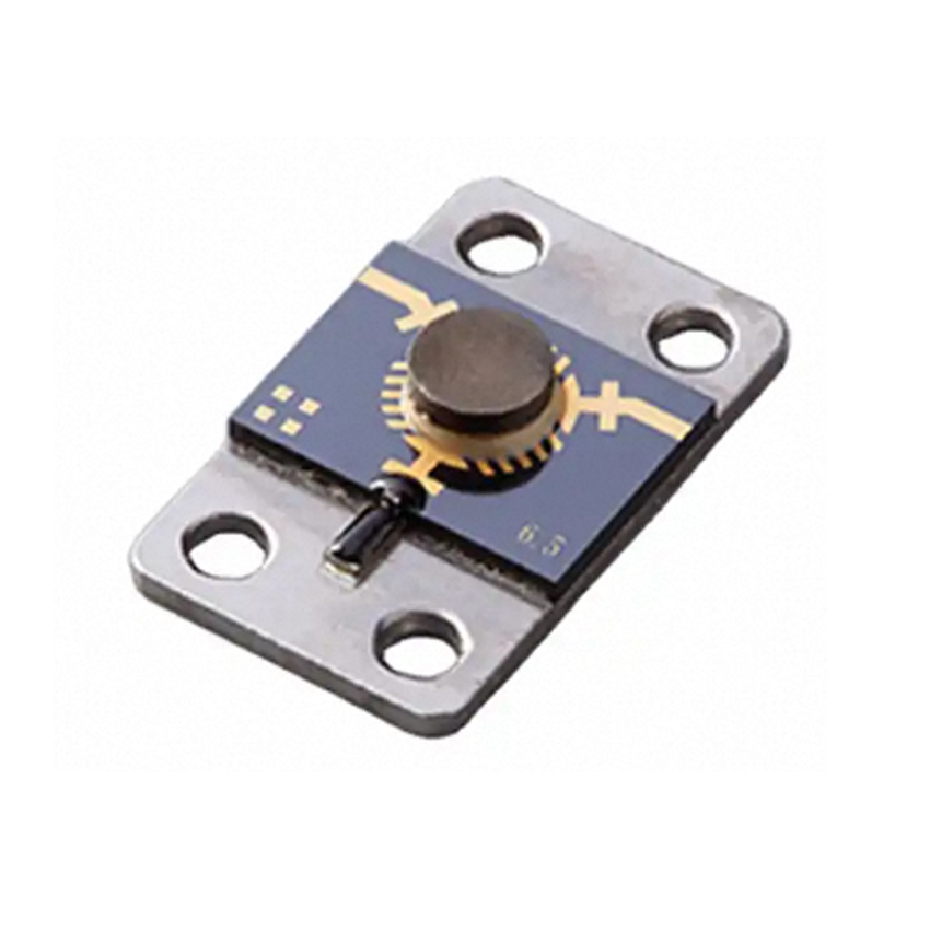


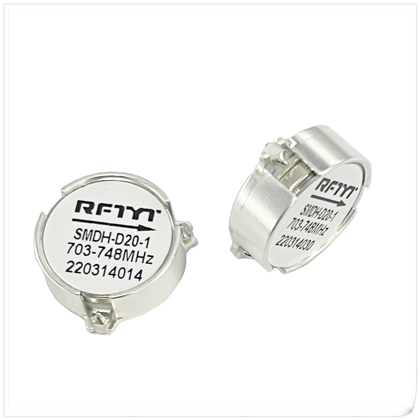
Microstrip Isolator
Data Sheet
| RFTYT 2.0-30GHz Microstrip Isolator | |||||||||
| Model | Frequency range (GHz) |
Insert loss (dB) (Max) |
Isolation (dB) (Min) |
VSWR (Max) |
Operation temperature (℃) |
Peak power (W) |
Reverse Power (W) |
Dimension W×L×Hmm |
Specification |
| MG1517-10 | 2.0~6.0 | 1.5 | 10 | 1.8 | -55~85 | 50 | 2 | 15.0*17.0*4.0 | |
| MG1315-10 | 2.7~6.2 | 1.2 | 1.3 | 1.6 | -55~85 | 50 | 2 | 13.0*15.0*4.0 | |
| MG1214-10 | 2.7~8.0 | 0.8 | 14 | 1.5 | -55~85 | 50 | 2 | 12.0*14.0*3.5 | |
| MG0911-10 | 5.0~7.0 | 0.4 | 20 | 1.2 | -55~85 | 50 | 2 | 9.0*11.0*3.5 | |
| MG0709-10 | 5.0~13 | 1.2 | 11 | 1.7 | -55~85 | 50 | 2 | 7.0*9.0*3.5 | |
| MG0675-07 | 7.0~13.0 | 0.8 | 15 | 1.45 | -55~85 | 20 | 1 | 6.0*7.5*3.0 | |
| MG0607-07 | 8.0-8.40 | 0.5 | 20 | 1.25 | -55~85 | 5 | 2 | 6.0*7.0*3.5 | |
| MG0675-10 | 8.0-12.0 | 0.6 | 16 | 1.35 | -55~+85 | 5 | 2 | 6.0*7.0*3.6 | |
| MG6585-10 | 8.0~12.0 | 0.6 | 16 | 1.4 | -40~+50 | 50 | 20 | 6.5*8.5*3.5 | |
| MG0719-15 | 9.0~10.5 | 0.6 | 18 | 1.3 | -30~+70 | 10 | 5 | 7.0*19.5*5.5 | |
| MG0505-07 | 10.7~12.7 | 0.6 | 18 | 1.3 | -40~+70 | 10 | 1 | 5.0*5.0*3.1 | |
| MG0675-09 | 10.7~12.7 | 0.5 | 18 | 1.3 | -40~+70 | 10 | 10 | 6.0*7.5*3.0 | |
| MG0506-07 | 11~19.5 | 0.5 | 20 | 1.25 | -55~85 | 20 | 1 | 5.0*6.0*3.0 | |
| MG0507-07 | 12.7~14.7 | 0.6 | 19 | 1.3 | -40~+70 | 4 | 1 | 5.0*7.0*3.0 | |
| MG0505-07 | 13.75~14.5 | 0.6 | 18 | 1.3 | -40~+70 | 10 | 1 | 5.0*5.0*3.1 | |
| MG0607-07 | 14.5~17.5 | 0.7 | 15 | 1.45 | -55~+85 | 5 | 2 | 6.0*7.0*3.5 | |
| MG0607-07 | 15.0-17.0 | 0.7 | 15 | 1.45 | -55~+85 | 5 | 2 | 6.0*7.0*3.5 | |
| MG0506-08 | 17.0-22.0 | 0.6 | 16 | 1.3 | -55~+85 | 5 | 2 | 5.0*6.0*3.5 | |
| MG0505-08 | 17.7~23.55 | 0.9 | 15 | 1.5 | -40~+70 | 2 | 1 | 5.0*5.0*3.5 | |
| MG0506-07 | 18.0~26.0 | 0.6 | 1 | 1.4 | -55~+85 | 4 | 5.0*6.0*3.2 | ||
| MG0445-07 | 18.5~25.0 | 0.6 | 18 | 1.35 | -55~85 | 10 | 1 | 4.0*4.5*3.0 | |
| MG3504-07 | 24.0~41.5 | 1 | 15 | 1.45 | -55~85 | 10 | 1 | 3.5*4.0*3.0 | |
| MG0505-08 | 25.0~31.0 | 1.2 | 15 | 1.45 | -40~+70 | 2 | 1 | 5.0*5.0*3.5 | |
| MG3505-06 | 26.0~40.0 | 1.2 | 11 | 1.6 | -55~+55 | 4 | 3.5*5.0*3.2 | ||
| MG0505-62 | 27.0~-31.0 | 0.7 | 17 | 1.4 | -40~+75 | 1 | 0.5 | 5.0*11.0*5.0 | |
| MG0511-10 | 27.0~31.0 | 1 | 18 | 1.4 | -55~+85 | 1 | 0.5 | 5.0*5.0*3.5 | |
| MG0505-06 | 28.5~30.0 | 0.6 | 17 | 1.35 | -40~+75 | 1 | 0.5 | 5.0*5.0*4.0 | |
Overview
The advantages of microstrip isolators include small size, light weight, small spatial discontinuity when integrated with microstrip circuits, and high connection reliability. Its relative disadvantages are low power capacity and poor resistance to electromagnetic interference.
Principles for selecting microstrip isolators:
1. When decoupling and matching between circuits, microstrip isolators can be selected.
2. Select the corresponding product model of the microstrip isolator based on the frequency range, installation size, and transmission direction used.
3. When the operating frequencies of both sizes of microstrip isolators can meet the usage requirements, products with larger volumes generally have higher power capacity.
Circuit connections for microstrip isolators:
The connection can be made using manual soldering with copper strips or gold wire bonding.
1. When purchasing copper strips for manual welding interconnection, the copper strips should be made into an Ω shape, and the solder should not soak into the forming area of the copper strip. Before welding, the surface temperature of the isolator should be maintained between 60 and 100 ° C.
2. When using gold wire bonding interconnection, the width of the gold strip should be smaller than the width of the microstrip circuit, and composite bonding is not allowed.