-

Dual Junction Circulator
Double junction Circulator is a passive device commonly used in the microwave and millimeter wave frequency bands. It can be divided into dual junction coaxial circulators and dual junction embedded circulators. It can also be divided into four port double junction circulators and three port double junction circulators based on the number of ports. It is composed of a combination of two annular structures. Its insertion loss and isolation are usually twice that of a single Circulator. If the isolation degree of a single Circulator is 20dB, the isolation degree of a double junction Circulator can often reach 40dB. However, there is not much change in the port standing wave.Coaxial product connectors are generally SMA, N, 2.92, L29, or DIN types. Embedded products are connected using ribbon cables.
Frequency range 10MHz to 40GHz,up to 500W power.
Military, space and commercial applications.
Low insertion loss, high isolation, high power handling.
Custom design available upon request.
-

SMT Circulator
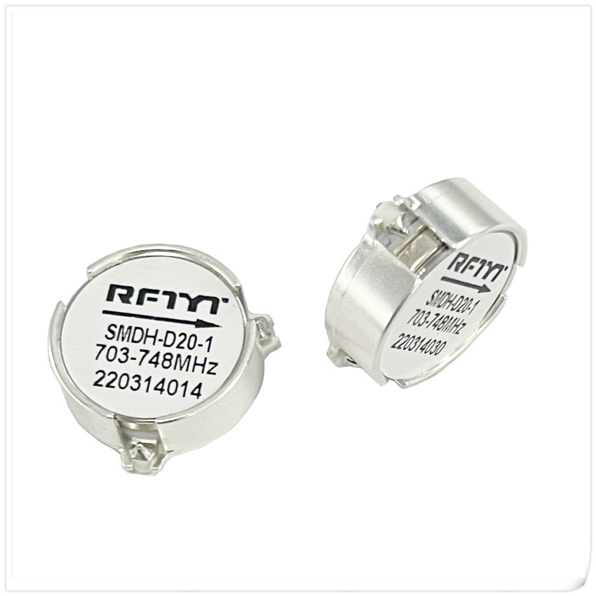
SMT surface mount Circulator is a type of ring-shaped device used for packaging and installation on a PCB (printed circuit board). They are widely used in communication systems, microwave equipment, radio equipment, and other fields. The SMD surface mount Circulator has the characteristics of being compact, lightweight, and easy to install, making it suitable for high-density integrated circuit applications. The following will provide a detailed introduction to the characteristics and applications of SMD surface mount Circulators.Firstly, the SMD surface mount Circulator has a wide range of frequency band coverage capabilities. They typically cover a wide frequency range, such as 400MHz-18GHz, to meet the frequency requirements of different applications. This extensive frequency band coverage capability enables SMD surface mount Circulators to perform excellently in multiple application scenarios.
Frequency range 200MHz to 15GHz.
Military, space and commercial applications.
Low insertion loss, high isolation, high power handling.
Custom design available upon request.
-

Drop in Isolator
The drop-in isolator is connected to the instrument equipment through strip line. Drop in isolator usually designed with small dimensions, it is easy to integrate into various devices and saves space. This miniaturized design makes drop in isolators suitable for applications with limited space.Drop in isolator could easy fixed on the PCB board by soldering which make it very convenient to use. The third port of the Drop-in isolator will be equipped with a chip attenuator to attenuate signal energy or chip termination to absorption signal energy. An Drop-in isolator is a protective device used in RF systems, whose main function is to transmit signals in a unidirectional manner to prevent antenna port signals from flowing back to the input (Tx) port.
Frequency range 10MHz to 40GHz,up to 2000W power.
Military, space and commercial applications.
Low insertion loss, high isolation, high power handling.
Custom design available upon request.
-

Waveguide Circulator
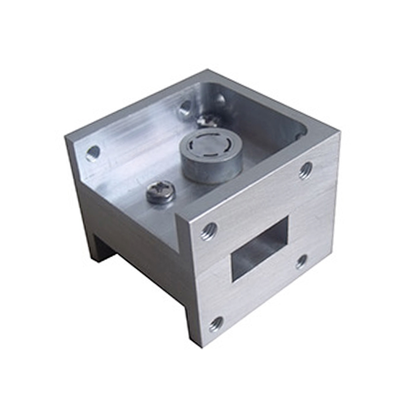
Waveguide Circulator is a passive device used in the RF and microwave frequency bands to achieve unidirectional transmission and isolation of signals. It has the characteristics of low insertion loss, high isolation, and broadband, and is widely used in communication, radar, antenna and other systems.The basic structure of a waveguide Circulator includes waveguide transmission lines and magnetic materials. A waveguide transmission line is a hollow metal pipeline through which signals are transmitted. Magnetic materials are usually ferrite materials placed at specific locations in waveguide transmission lines to achieve signal isolation.
Frequency range 5.4 to 110GHz.
Military, space and commercial applications.
Low insertion loss, high isolation, high power handling.
Custom design available upon request.
-

RFT50-10WT0404 DC-8.0GHz Chip Termination
Outline Drawing (Unit: mm/inch) Dimensional tolerance: 5% unless otherwise stated Typical Performance: Installation method Power De-rating Reflow time and temperature diagram P/N Designation Matters needing attention ■ After the storage period of newly purchased parts exceeds 6 months, attention should be paid to their weldability before use. It is recommended to store in vacuum packaging. ■ Drill out the hot hole on the PCB and fill the solder. ■ Reflow welding is preferred for bottom w... -

Flanged Resistor
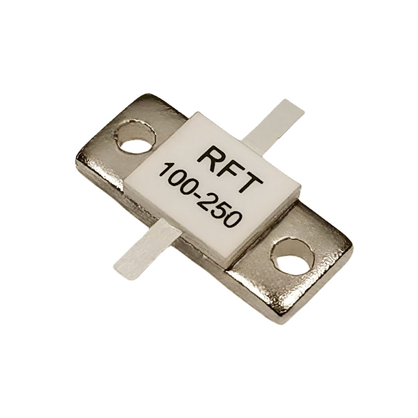
Flanged resistor is one of the commonly used passive components in electronic circuits, which has the function of balancing the circuit.It achieves stable operation of the circuit by adjusting the resistance value in the circuit to achieve a balanced state of current or voltage. It plays an important role in electronic devices and communication systems.In a circuit, when the resistance value is imbalanced, there will be uneven distribution of current or voltage, leading to instability of the circuit. Flanged resistor can balance the distribution of current or voltage by adjusting the resistance in the circuit. The flange balance resistor adjusts the resistance value in the circuit to evenly distribute current or voltage in each branch, thus achieving balanced operation of the circuit.
-

-

RFT50N-10CT2550 DC~6.0GHz Chip Termination
Typical Performance: Installation method Power De-rating Reflow time and temperature diagram: P/N Designation Reflow time and temperature diagram ■ After the storage period of newly purchased parts exceeds 6 months, attention should be paid to their weldability before use. It is recommended to store in vacuum packaging. ■ Drill out the hot hole on the PCB and fill the solder. ■ Reflow welding is preferred for bottom welding, see Introduction to Reflow welding. ■ Add air cooling or water co... -

-

3-PD06-F8318-S/500-8000MHz 500-8000 MHz RF Power Divider
Features and Electrical specifications:
-

TG5050AS 1.25 to 3.0GHz Coaxial Isolator
RFTYT offers a broad range of TG5050AS 1.25 to 3.0GHz Coaxial Isolator, RF Circulators, RF Resistor, Attenuator, Termination, RF Filters, Power Divider, Splitter, Duplexer, Triplexer, Hybrid Combiner, RF Coupler. Manufacturer and factory of TG5050AS 1.25 to 3.0GHz Coaxial Isolator.
-

160 to 300MHz Coaxial Circulator TH5258EN N Type / TH5258ES SMA Type
Order Examples Connector Type SMA Type Connector Options N Type Connector Options Port 1 Port 2 Port 3 Abbreviation Port 1 Port 2 Port 3 Abbreviation K K K S K K K N K J J SKJJ K J J NKJJ J K J SJKJ J K J NJKJ K K J SKKJ K K J NKKJ J J J SJ J J J NJ SMA Type Connector Options N Type Connector Options Port 1 Port 2 Port 3 Abbreviation Port 1 Port 2 Port ...


