-

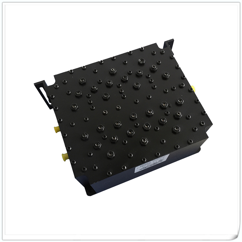
HPF-11.7G15A-S High Pass Filter RF Filter
Outline Drawing (Unit: mm) -
Microwave series
straight waveguide Tube type Frequency Range (GHz) VSWR Inflation Pressure (Mpa) BJ14 1.13-1.73 ≤ 1.05 ≤ 0.3 BJ18 1.45-2.20 ≤ 1.05 ≤ 0.3 BJ22 1.72-2.61 ≤ 1.05 ≤ 0.3 BJ26 2.17-3.3 ≤ 1.05 ≤ 0.3 BJ32 2.60-3.95 ≤ 1.05 ≤ 0.3 BJ40 3.22-4.90 ≤ 1.05 ≤ 0.3 BJ48 3.94-5.99 ≤ 1.05 ≤ 0.3 BJ58 4.64-7.05 ≤ 1.05 ≤ 0.3 BJ70 5.38-8.17 ≤ 1.1 ≤ 0.3 BJ84 6.57-9.99 ≤ 1.1 ≤ 0.3 BJ100 8.20-12.5 ≤ 1.1 BJ120 9.84-15.0 ≤ 1.1 BJ140 11.9-18.0 ≤ 1.1 BJ220 17.6-26.7 ≤ 1.1... -

LPF-DCM2970A-S Low Pass Filter RF Filter
Outline Drawing (Unit: mm) -

LPF-DCM1000A-S Low Pass Filter RF Filter
Outline Drawing (Unit: mm) -

LPF-DCM2000A-S Low Pass Filter RF Filter
Outline Drawing (Unit: mm) -

LPF-DCM4200A-S Low Pass Filter RF Filter
Outline Drawing (Unit: mm) -

LPF-DCM5800A-S Low Pass Filter RF Filter
Outline Drawing (Unit: mm) -

LPF-DCG23.6A-S Low Pass Filter RF Filter
Outline Drawing (Unit: mm) -

LPF-DCG13.6A-S Low Pass Filter RF Filter
Outline Drawing (Unit: mm) -

Band Pass Filter
A cavity duplexer is a special type of duplexer used in wireless communication systems to separate transmitted and received signals in the frequency domain. The cavity duplexer consists of a pair of resonant cavities, each specifically responsible for communication in one direction.
The working principle of a cavity duplexer is based on frequency selectivity, which uses a specific resonant cavity to selectively transmit signals within the frequency range. Specifically, when a signal is sent into a cavity duplexer, it is transmitted to a specific resonant cavity and amplified and transmitted at the resonant frequency of that cavity. At the same time, the received signal remains in another resonant cavity and will not be transmitted or interfered with.
Custom design available upon request.
-

Coaxial Fixed Attenuator
Coaxial attenuator is a device used to reduce the signal power in a coaxial transmission line. It is commonly used in electronic and communication systems to control signal strength, prevent signal distortion, and protect sensitive components from excessive power.
Coaxial attenuators are generally composed of connectors (usually using SMA, N, 4.30-10, DIN, etc.), attenuation chips or chipsets (can be divided into flange type: usually selected for use in lower frequency bands, rotary type can achieve higher frequencies) Heat sink (Due to the use of different power attenuation chipsets, the heat emitted cannot be dissipated by itself, so we need to add a larger heat dissipation area to the chipset.Using better heat dissipation materials can make the attenuator work more stably.)
Custom design available upon request.
-

A5 RF Variable Attenuator DC-26.5GHz RF Attenuator
specs Model Freq. Range Attenuation & VSWR Insertion Loss Attenuation Tolerance GHz Step (max) dB(max) dB RKTX2-1-9-8.0-A5 DC-8.0 0-9dB 1.4 0.8 ±0.6 RKTX2-1-9-12.4-A5 DC-12.4 1dB Step 1.5 1 ±0.8 RKTX2-1-9-18.0-A5 DC-18.0 1.6 1.2 ±1.0 RKTX2-1-9-26.5-A5 DC-26.5 1.75 1.8 ±1.0 RKTX2-1-90-8.0-A5 DC-8.0 0-90dB 1.4 1 ±1.5(10-60dB) RKTX2-1-90-12.4-A5 DC-12.4 10dB Step 1.5 1.2 ±2.5 or 3.5%(70-90dB) RKTX2-1-90-18.0-A5 DC-18.0 1.6 1.5 RKTX10-1-9-8.0-A5 DC-8.0 0-9dB 1.4 ...


