-

Flanged Termination
Flanged terminations are installed at the end of a circuit, which absorb signals transmitted in the circuit and prevent signal reflection, thereby affecting the transmission quality of the circuit system.The flanged terminal is assembled by welding a single lead terminal resistor with flanges and patches. The flange size is usually designed based on the combination of installation holes and terminal resistance dimensions. Customization can also be made according to the customer’s usage requirements.
-

RFTXXN-100AJ8957-3 Leaded Attenuator DC~3.0GHz RF Attenuator
Model RFTXXN-100AJ8957-3 (XX=Attenuation value) Impedance 50 Ω Frequency Range DC~3.0GHz VSWR 1.20 max Rated Power 100 W Attenuation Value 13、20、30dB Attenuation Tolerance ±1.0dB Temperature coefficient <150ppm/℃ Substrate Material AlN Porcelain Hat Material Medium Lead 99.99% Sterling Silver Resistance Technology Thick Film Operating Temperature -55 to +150°C (See de Power De-rating) Outline Drawing (Unit: mm/inch) Lead length can be customized accordi... -

Microstrip Attenuator
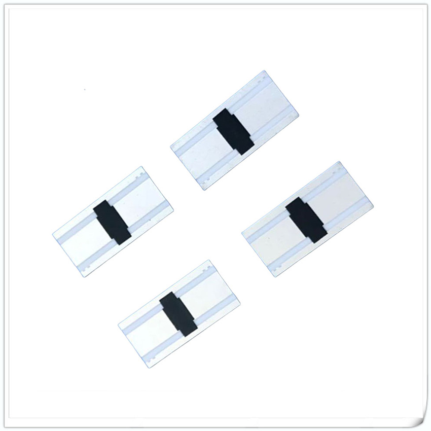
Microstrip Attenuator is a device that plays a role in signal attenuation within the microwave frequency band. Making it into a fixed attenuator is widely used in fields such as microwave communication, radar systems, satellite communication, etc., providing controllable signal attenuation function for circuits.Microstrip Attenuator chips, unlike the commonly used patch attenuation chips, need to be assembled into a specific size air hood using coaxial connection to achieve signal attenuation from input to output.
Custom design available upon request.
-

RFT20N-60AM6363-6 Leaded Attenuator DC~6.0GHz RF Attenuator
Model RFT20N-60AM6363-6 (XX=Attenuation value) Impedance 50 Ω Frequency Range DC~6.0GHz VSWR 1.25 max Rated Power 60 W Attenuation Value 20dB Attenuation Tolerance ±0.8 dB Temperature coefficient <150ppm/℃ Substrate Material AlN Porcelain Hat Material Al2O3 Lead 99.99% Sterling Silver Resistance Technology Thick Film Operating Temperature -55 to +150°C (See de Power De-rating) Outline Drawing (Unit: mm/inch) Lead length can be customized according to cust... -

RFTXX-60AM6363B-3 Leaded Attenuator DC~3.0GHz RF Attenuator
Model RFTXX-60AM6363B-3 (XX=Attenuation value) Impedance 50 Ω Frequency Range DC~3.0GHz VSWR 1.25 max Rated Power 60 W Attenuation Value 01-10dB/16dB/20dB Attenuation Tolerance ±0.6dB/±0.8dB/±1.0dB Temperature coefficient <150ppm/℃ Substrate Material BeO Porcelain Hat Material Al2O3 Lead 99.99% Sterling Silver Resistance Technology Thick Film Operating Temperature -55 to +150°C (See de Power De-rating) Outline Drawing (Unit: mm/inch) Lead length can be cu... -

RFTXXA-05AM0404-3 Leaded Attenuator DC~3.0GHz RF Attenuator
Model RFTXXA-05AM0404-3 (XX=Attenuation value) Impedance 50 Ω Frequency Range DC~3.0GHz VSWR 1.20 max Rated Power 5 W Attenuation Value(dB) 01-10/15, 17, 20/25,30 Attenuation Tolerance(dB) ±0.6/±0.8/±1.0 Temperature coefficient <150ppm/℃ Substrate Material Al2O3 Porcelain Hat Material Al2O3 Lead 99.99% Sterling Silver Resistance Technology Thick Film Operating Temperature -55 to +150°C (See de Power De-rating) Outline Drawing (Unit: mm/inch) Lead length ... -

Microstrip Circulator
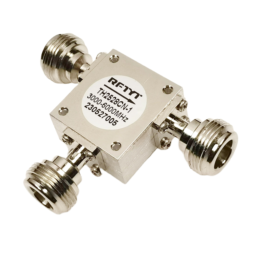
Microstrip Circulator is a commonly used RF microwave device used for signal transmission and isolation in circuits. It uses thin film technology to create a circuit on top of a rotating magnetic ferrite, and then adds a magnetic field to achieve it. The installation of microstrip annular devices generally adopts the method of manual soldering or gold wire bonding with copper strips.The structure of microstrip circulators is very simple, compared to coaxial and embedded circulators. The most obvious difference is that there is no cavity, and the conductor of the microstrip Circulator is made by using a thin film process (vacuum sputtering) to create the designed pattern on the rotary ferrite. After electroplating, the produced conductor is attached to the rotary ferrite substrate. Attach a layer of insulating medium on top of the graph, and fix a magnetic field on the medium. With such a simple structure, a microstrip circulator has been fabricated.
Frequency range 2.7 to 40GHz.
Military, space and commercial applications.
Low insertion loss, high isolation, high power handling.
Custom design available upon request.
-

Broadband Circulator
Broadband Circulator is an important component in RF communication systems, providing a series of advantages that make it very suitable for various applications. These Circulators provide broadband coverage, ensuring effective performance over a wide frequency range. With their ability to isolate signals, they can prevent interference from out of band signals and maintain the integrity of in band signals.One of the main advantages of broadband circulators is their excellent high isolation performance. At the same time, these ring-shaped devices have good port standing wave characteristics, reducing reflected signals and maintaining stable signal transmission.
Frequency range 56MHz to 40GHz,BW up to 13.5GHz.
Military, space and commercial applications.
Low insertion loss, high isolation, high power handling.
Custom design available upon request.
-

RFTXX-60CA6363B-3 Chip Attenuator DC~3.0GHz RF Attenuator
Model RFTXX-60CA6363B-3 (XX= Attenuation value) Resistance Range 50 Ω Frequency Range DC~3.0GHz VSWR 1.25 max Power 60 W Attenuation Value(dB) 01-10dB/11-20dB/21-30dB Attenuation Tolerance(dB) ±0.6dB/±0.8dB/±1.0dB Temperature Coefficient <150ppm/℃ Substrate Material BeO Resistance Technology Thick Film Operating Temperature -55 to +150°C (See de Power De-rating) Installation method Power De-rating Reflow soldering time & Temperature diagram P/N Designation ... -

RFTXXN-20CA5025C-3 Chip Attenuator DC~3.0GHz RF Attenuator
Model RFTXXN-20CA5025C-3 (XX= Attenuation value) Resistance Range 50 Ω Frequency Range DC~3.0GHz VSWR 1.25 max Power 20 W Attenuation Value(dB) 01-10dB/11-20dB/21-30dB Attenuation Tolerance(dB) ±0.6dB/±0.8dB/±1.0dB Temperature Coefficient <150ppm/℃ Substrate Material AlN Resistance Technology Thick Film Operating Temperature -55 to +150°C (See de Power De-rating) Typical Performance: 2dB Graph 20dB Graph 6dB Graph 30dB Graph Installation method... -

RFTXXN-10CA5025C-6 Chip Attenuator DC~6.0GHz RF Attenuator
Model RFTXXN-10CA5025C-6 (XX= Attenuation value) Resistance Range 50 Ω Frequency Range DC~6.0GHz VSWR 1.25 max Power 10 W Attenuation Value(dB) 01-10dB/11-20dB Attenuation Tolerance(dB) ±0.6dB/±0.8dB Temperature Coefficient <150ppm/℃ Substrate Material AlN Resistance Technology Thick Film Operating Temperature -55 to +150°C (See de Power De-rating) Typical Performance: 6dB Graph 20dB Graph Installation method Power De-rating Reflow soldering time & ... -

RFTXX-250RM1313K Leaded Resistor RF Resistor
Model RFTXX-250RM1313K Power 250 W Resistance XX Ω~ (10-1000Ω Customizable) Resistance Tolerance ±5% Capacitance 2.0 PF@100Ω Temperature Coefficient <150ppm/℃ Substrate BeO Cover AL2O3 Lead Copper silver plating Resistive Element Thick Film Operating Temperature -55 to +150°C (See de Power De-rating) Suggested mounting procedures Power De-rating Reflow Profile P/N Designation Use attention ■ After the storage period of newly purchased components exceeds 6 mon...


