-

RFTXX-30CR6363C Chip Resistor RF Resistor
Model RFTXX-30CR6363C Power 30W Resistance XX Ω (10~3000Ω Customizable) Resistance Tolerance ±5% Temperature Coefficient <150ppm/℃ Substrate BeO Resistive Element Thick Film Operating Temperature -55 to +150°C (See de Power De-rating) Suggested mounting procedures Power De-rating Reflow Profile P/N Designation Use attention ■ After the storage period of newly purchased parts exceeds 6 months, attention shall be paid to the weldability before use. It is recommended ... -

RFTXX-30CR2550W Chip Resistor RF Resistor
Model RFTXX-30CR2550W Power 30 W Resistance XX Ω (10~3000Ω Customizable) Resistance Tolerance ±5% Temperature Coefficient <150ppm/℃ Substrate BeO Resistive Element Thick Film Operating Temperature -55 to +150°C (See de Power De-rating) Suggested mounting procedures Power De-rating Reflow Profile P/N Designation Use attention ■ After the storage period of newly purchased parts exceeds 6 months, attention shall be paid to the weldability before use. It is recommended... -

RFTXX-30CR2550TA Chip Resistor RF Resistor
Model RFTXX-30CR2550TA Power 30W Resistance XX Ω (10~3000Ω Customizable) Resistance Tolerance ±5% Temperature Coefficient <150ppm/℃ Substrate BeO Resistive Element Thick Film Operating Temperature -55 to +150°C (See de Power De-rating) Suggested mounting procedures Power De-rating Reflow Profile P/N Designation Use attention ■ After the storage period of newly purchased parts exceeds 6 months, attention shall be paid to the weldability before use. It is recommended... -

RFTXX-30RM2006 Flanged Resistor RF Resistor
Model RFTXX-30RM2006 Power 30 W Resistance XX Ω (10~2000Ω Customizable) Resistance Tolerance ±5% Capacitance 2.6 PF@100Ω Temperature Coefficient <150ppm/℃ Substrate BeO Cover AL2O3 Mounting Flange Brass Lead 99.99% pure silver Resistive Element Thick Film Operating Temperature -55 to +150°C (See de Power De-rating) Outline Drawing (Unit: mm) The length of lead wire can meet the customer’s requirements Size Tolerance:5% unless otherwise stated Suggest... -

RFTXX-30RM1306 RF Resistor
Model RFTXX-30RM1306 Power 30 W Resistance XX Ω (10~2000Ω Customizable) Resistance Tolerance ±5% Capacitance 2.6 PF@100Ω Temperature Coefficient <150ppm/℃ Substrate BeO Cover AL2O3 Mounting Flange Brass Lead 99.99% pure silver Resistive Element Thick Film Operating Temperature -55 to +150°C (See de Power De-rating) Outline Drawing (Unit: mm) The length of lead wire can meet the customer’s requirements Size Tolerance:5% unless otherwise stated Suggest... -

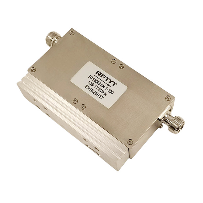
Dual Junction Isolator
A dual junction isolator is a passive device commonly used in microwave and millimeter-wave frequency bands to isolate reverse signals from the antenna end. It is composed of the structure of two isolators. Its insertion loss and isolation are typically twice than a single isolator. If the isolation of a single isolator is 20dB, the isolation of a double-junction isolator can often be 40dB. The port VSWR does not change much.In the system, when the radio frequency signal is transmitted from the input port to the first ring junction, because one end of the first ring junction is equipped with a radio frequency resistor, its signal can only be transmitted to the input end of the second ring junction. The second loop junction is the same as the first one, with RF resistors installed, the signal will be passed to the output port, and its isolation will be the sum of the isolation of the two loop junctions. The reverse signal returning from the output port will be absorbed by the RF resistor in the second ring junction. In this way, a large degree of isolation between the input and output ports is achieved, effectively reducing reflections and interference in the system.
Frequency range 10MHz to 40GHz,up to 500W power.
Military, space and commercial applications.
Low insertion loss, high isolation, high power handling.
Custom design available upon request.
-

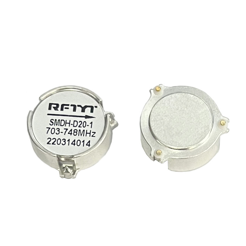
SMT / SMD Isolator
SMD isolator is an isolation device used for packaging and installation on a PCB (printed circuit board). They are widely used in communication systems, microwave equipment, radio equipment, and other fields. SMD isolators are small, lightweight, and easy to install, making them suitable for high-density integrated circuit applications. The following will provide a detailed introduction to the characteristics and applications of SMD isolators.Firstly, SMD isolators have a wide range of frequency band coverage capabilities. They typically cover a wide frequency range, such as 400MHz-18GHz, to meet the frequency requirements of different applications. This extensive frequency band coverage capability enables SMD isolators to perform excellently in multiple application scenarios.
Frequency range 200MHz to 15GHz.
Military, space and commercial applications.
Low insertion loss, high isolation, high power handling.
Custom design available upon request.
-

RFTXX-20RM0904 RF Resistor
Model RFTXX-20RM0904 Power 20 W Resistance XX Ω (10~3000Ω Customizable) Resistance Tolerance ±5% Capacitance 1.2 PF@100Ω Temperature Coefficient <150ppm/℃ Substrate BeO Cover AL2O3 Mounting Flange Brass Lead 99.99% pure silver Resistive Element Thick Film Operating Temperature -55 to +150°C (See de Power De-rating) Outline Drawing (Unit: mm) The length of lead wire can meet the customer’s requirements Size Tolerance:5% unless otherwise stated Suggest... -

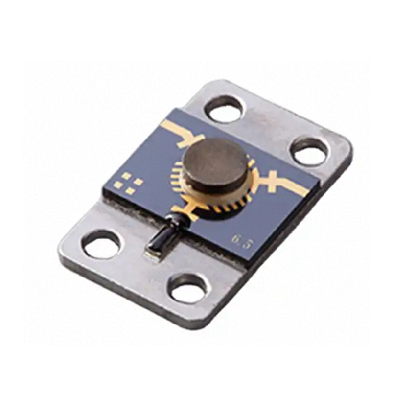
Microstrip Isolator
Microstrip isolators are a commonly used RF and microwave device used for signal transmission and isolation in circuits. It uses thin film technology to create a circuit on top of a rotating magnetic ferrite, and then adds a magnetic field to achieve it. The installation of microstrip isolators generally adopts the method of manual soldering of copper strips or gold wire bonding. The structure of microstrip isolators is very simple, compared to coaxial and embedded isolators. The most obvious difference is that there is no cavity, and the conductor of the microstrip isolator is made by using a thin film process (vacuum sputtering) to create the designed pattern on the rotary ferrite. After electroplating, the produced conductor is attached to the rotary ferrite substrate. Attach a layer of insulating medium on top of the graph, and fix a magnetic field on the medium. With such a simple structure, a microstrip isolator has been fabricated.
Frequency range 2.7 to 43GHz
Military, space and commercial applications.
Low insertion loss, high isolation, high power handling.
Custom design available upon request.
-

CT-50W-FH6080-IP65-DINJ-3G DC~3.0GHz Low Intermodulation Termination
Model CT-50W-FH6080-IP65-DINJ-3G Frequency Range DC~3.0GHz VSWR 1.20 Max PIM3 ≥120dBc@2*33dBm Power 50W Impedance 50 Ω Connector Type DIN-M (J) Waterproof Grade IP65 Dimension 60×60×80mm Operating Temperature -55 ~ +125°C (See de Power De-rating) Color Black Weight Around 410 g Use attention Power De-rating P/N Designation -

RFTXX-20RM1304 RF Resistor
Model RFTXX-20RM1304 Power 20 W Resistance XX Ω (10~3000Ω Customizable) Resistance Tolerance ±5% Capacitance 1.2 PF@100Ω Temperature Coefficient <150ppm/℃ Substrate BeO Cover AL2O3 Mounting Flange Brass Lead 99.99% pure silver Resistive Element Thick Film Operating Temperature -55 to +150°C (See de Power De-rating) Outline Drawing (Unit: mm) The length of lead wire can meet the customer’s requirements Size Tolerance:5% unless otherwise stated Sugges... -


