Products
RF Coupler (3dB, 10dB, 20dB, 30dB)
Data Sheet
| RF Couplers 6dB Coupler |
|||||||
| Model & Data sheet | Freq. Range | Degree of coupling | Coupling Sensitivity | Insertion Loss (Max) | Directivity | VSWR (Max) | Rated Power |
| CP06-F2586-S/0.698-2.2 | 0.698-2.2GHz | 6±1dB | ±0.3dB | 0.4dB | 20dB | 1.2 | 50W |
| CP06-F1585-S/0.698-2.7 | 0.698-2.7GHz | 6±1dB | ±0.8dB | 0.65dB | 18dB | 1.3 | 50W |
| CP06-F1573-S/1-4 | 1-4GHz | 6±1dB | ±0.4dB | 0.4dB | 20dB | 1.2 | 50W |
| CP06-F2155-N/2-6 | 2-6GHz | 6±1dB | - | 1.5dB | 18dB | 1.35 | 30W |
| CP06-F1543-S/2-8 | 2-8GHz | 6±1dB | ±0.35dB | 0.4dB | 20dB | 1.2 | 50W |
| CP06-F1533-S/6-18 | 6-18GHz | 6±1dB | ±0.8dB | 0.8dB | 12dB | 1.5 | 50W |
| CP06-F1528-G/27-32 | 27-32GHz | 6±1dB | ±0.7dB | 1.2dB | 10dB | 1.6 | 10W |
| 10dB Coupler |
|||||||
| Model & Data sheet | Freq. Range | Degree of coupling | Coupling Sensitivity | Insertion Loss(Max) | Directivity | VSWR (Max) | Rated Power |
| CP10-F1511-S/0.5-6 | 0.5-6GHz | 10±1dB | ±0.7dB | 0.7dB | 18dB | 1.2 | 50W |
| CP10-F1511-S/0.5-8 | 0.5-8GHz | 10±1dB | ±0.7dB | 0.7dB | 18dB | 1.2 | 50W |
| CP10-F1511-S/0.5-18 | 0.5-18GHz | 10±1dB | ±1.0dB | 1.2dB | 12dB | 1.2 | 50W |
| CP10-F2586-S/0.698-2.2 | 0.698-2.2GHz | 10±1dB | ±0.5dB | 0.4dB | 20dB | 1.2 | 50W |
| CP10-F1585-S/0.698-2.7 | 0.698-2.7GHz | 10±1dB | ±1.0dB | 0.5dB | 20dB | 1.2 | 50W |
| CP10-F1573-S/1-4 | 1-4GHz | 10±1dB | ±0.4dB | 0.5dB | 20dB | 1.2 | 50W |
| CP10-F1573-S/1-18 | 1-18GHz | 10±1dB | ±1.0dB | 1.2dB | 12dB | 1.6 | 50W |
| CP10-F1543-S/2-8 | 2-8GHz | 10±1dB | ±0.4dB | 0.4dB | 20dB | 1.2 | 50W |
| CP10-F1543-S/2-18 | 2-18GHz | 10±1dB | ±1.0dB | 0.7dB | 12dB | 1.5 | 50W |
| CP10-F1533-S/4-18 | 4-18GHz | 10±1dB | ±0.7dB | 0.6dB | 12dB | 1.5 | 50W |
| CP10-F1528-G/6-40 | 6-40GHz | 10±1dB | ±1.0dB | 1.2dB | 10dB | 1.6 | 20W |
| CP10-F1528-G/18-40 | 18-40GHz | 10±1dB | ±1.0dB | 1.2dB | 12dB | 1.6 | 20W |
| CP10-F1528-G/27-32 | 27-32GHz | 10±1dB | ±1.0dB | 1.0dB | 12dB | 1.5 | 20W |
| 20dB Coupler |
|||||||
| Model & Data sheet | Freq. Range | Degree of coupling | Coupling Sensitivity | Insertion Loss(Max) | Directivity | VSWR (Max) | Rated Power |
| CP20F1511-S/0.5-6 | 0.5-6GHz | 20±1dB | ±0.8dB | 0.7dB | 18dB | 1.2 | 50W |
| CP20-F1511-S/0.5-8 | 0.5-8GHz | 20±1dB | ±0.8dB | 0.7dB | 18dB | 1.2 | 50W |
| CP20-F1511-S/0.5-18 | 0.5-18GHz | 20±1dB | ±1.0dB | 1.2dB | 10dB | 1.6 | 30W |
| CP20-F2586-S/0.698-2.2 | 0.698-2.2GHz | 20±1dB | ±0.6dB | 0.4dB | 20dB | 1.2 | 50W |
| CP20-F1585-S/0.698-2.7 | 0.698-2.7GHz | 20±1dB | ±0.7dB | 0.4dB | 20dB | 1.3 | 50W |
| CP20-F1573-S/1-4 | 1-4GHz | 20±1dB | ±0.6dB | 0.5dB | 20dB | 1.2 | 50W |
| CP20-F1573-S/1-18 | 1-18GHz | 20±1dB | ±1.0dB | 0.9dB | 12dB | 1.6 | 50w |
| CP20-F1543-S/2-8 | 2-8GHz | 20±1dB | ±0.6dB | 0.5dB | 20dB | 1.2 | 50W |
| CP20-F1543-S/2-18 | 2-18GHz | 20±1dB | ±1.0dB | 1.2dB | 12dB | 1.5 | 50W |
| CP201533-S/4-18 | 4-18GHz | 20±1dB | ±1.0dB | 0.6dB | 12dB | 1.5 | 50W |
| CP20-F1528-G/6-40 | 6-40GHz | 20±1dB | ±1.0dB | 1.0dB | 10dB | 1.6 | 20W |
| CP20-F1528-G/18-40 | 18-40GHz | 20±1dB | ±1.0dB | 1.2dB | 12dB | 1.6 | 20W |
| CP20-F1528-G/27-32 | 27-32GHz | 20±1dB | ±1.0dB | 1.2dB | 12dB | 1.5 | 20W |
| 30dB Coupler |
|||||||
| Model & Data sheet | Freq. Range | Degree of coupling | CouplingSensitivity | Insertion Loss(Max) | Directivity | VSWR (Max) | Rated Power |
| CP30-F1511-S/0.5-6 | 0.5-6GHz | ±30dB | ±1.0dB | 1.0dB | 18dB | 1.25 | 50W |
| CP30-F1511-S/0.5-8 | 0.5-8GHz | ±30dB | ±1.0dB | 1.0dB | 18dB | 1.25 | 50W |
| CP30-F1511-S/0.5-18 | 0.5-18GHz | ±30dB | ±1.0dB | 1.2dB | 10dB | 1.6 | 50W |
| CP30-F1573-S/1-4 | 1-4GHz | ±30dB | ±0.7dB | 0.5dB | 20dB | 1.2 | 50W |
| CP30-F1573-S/1-18 | 1-18GHz | ±30dB | ±1.0dB | 1.2dB | 12dB | 1.6 | 50W |
| CP30-F1543-S/2-8 | 2-8GHz | ±30dB | ±1.0dB | 0.4dB | 20dB | 1.2 | 50W |
| CP30-F1543-S/2-18 | 2-18GHz | ±30dB | ±1.0dB | 0.8dB | 12dB | 1.5 | 50W |
| CP30-F1533-S/4-18 | 4-18GHz | ±30dB | ±1.0dB | 0.6dB | 12dB | 1.5 | 50W |
Overview
The main indicators we consider when selecting a coupler include coupling degree, isolation degree, insertion loss, directionality, input output standing wave ratio, frequency range, power size, in band amplitude, and input impedance.
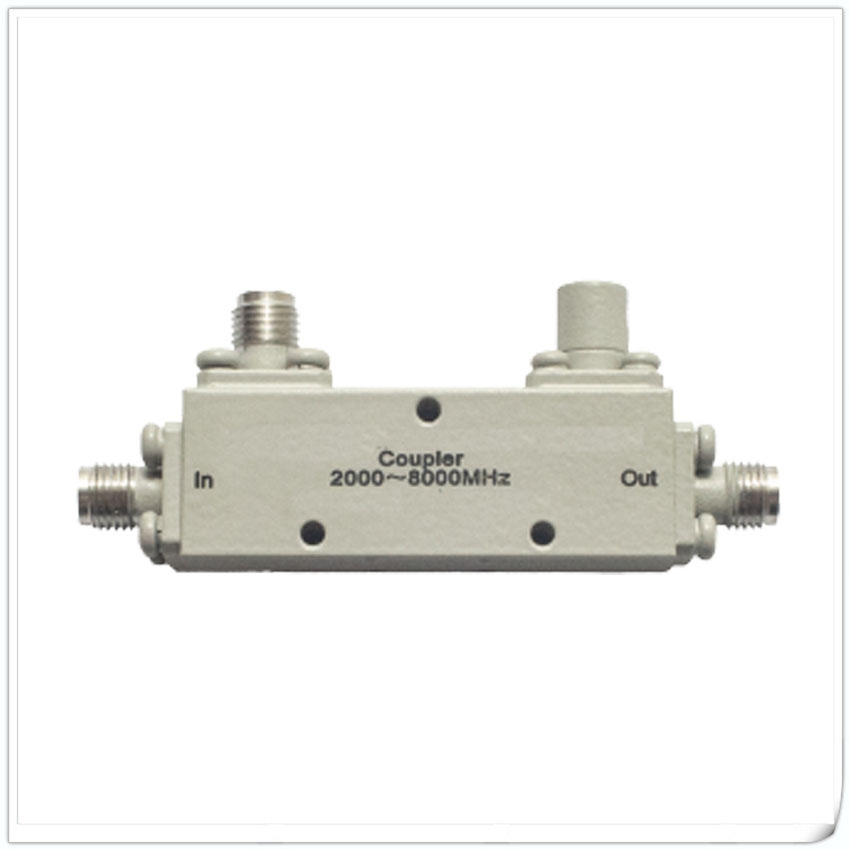
The main function of the coupler is to couple a portion of the input signal to the coupling port, while the remaining portion of the signal is output from another port.
In practical applications, couplers have many uses. It can be used for signal allocation and power detection, such as distributing signals to multiple receivers or transmitters in antenna systems. It can also be used in testing and measuring equipment to calibrate the strength and phase of signals. In addition, couplers can also be used in fields such as modulation, demodulation, and interference analysis.
Both couplers and power dividers can achieve the allocation of input signals, but they are fundamentally different. The output signals of the power divider and output ports have the same amplitude and phase, while the coupler is the opposite, and the signals between each output port have different amplitudes and phases. So when choosing, it is necessary to make the correct choice based on the actual situation.
The couplers sold by our company are mainly divided into 3dB couplers, 10dB couplers, 20dB couplers, 30dB couplers, and low intermodulation couplers. Welcome customers to choose according to their actual applications. If you have any questions, please contact our sales personnel for detailed inquiries.


