products

RF Directional Coupler

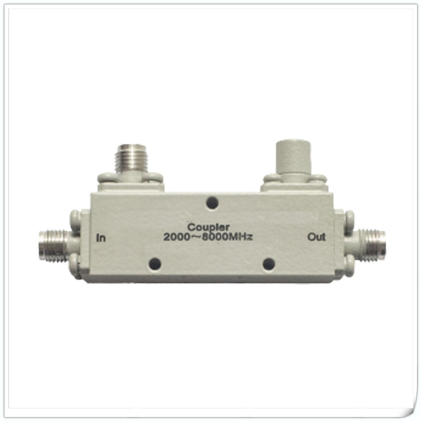
  • 1-CP10-F1511-S 0.5-6GHz RF Directional Coupler

    1-CP10-F1511-S 0.5-6GHz RF Directional Coupler

    Features and Electrical specifications:

    Model CP10-F1511-S/0.5-6GHz
    Frequency Range 0.5~6GHz
    Insertion Loss ≤±0.7dB(Excluding 0.45dB coupling loss)
    Nominal Coupling 10±1dB
    Coupling Sensitivity ≤±0.7dB
    Directivity ≥18dB
    VSWR 1.20 Max
    Rated Power 50W
    Impedance 50 Ω
    Connector Type SMA-F
    Dimension 113x15x11 mm
    Surface Finishing Grey Painting
    Operating Temperature -55 ~ +85°C
    ROHS Compliant Yes
  • 1-CP08-F2155-N 2-6GHz RF Directional Coupler

    1-CP08-F2155-N 2-6GHz RF Directional Coupler

    Features and Electrical specifications:

    Model CP08-F2155-N/2-6GHz
    Frequency Range 2.0~6.0 GHz
    Insertion Loss ≤1.5dB
    Nominal Coupling 6±1dB
    Directivity ≥18dB
    VSWR 1.35 Max
    Rated Power 30W
    Impedance 50 Ω
    Connector Type N-F
    Dimension 55.0×21.0×22.3 mm
    Operating Temperature -55 ~ +85°C
    ROHS Compliant Yes
  • 7-CP06-F1528-G 27-32GHz RF Directional Coupler

    7-CP06-F1528-G 27-32GHz RF Directional Coupler

    Features and Electrical specifications:

    Model CP06-F1528-G/27-32GHz
    Frequency Range 27~32GHz
    Insertion Loss 1.2dB(Excluding 1.25dB coupling loss)
    Nominal Coupling 6±1dB
    Coupling Sensitivity ≤±0.7dB
    Directivity 10dB
    VSWR 1.60 Max
    Rated Power 10W
    Impedance 50 Ω
    Connector Type 2.92-F
    Dimension 28x15x11 mm
    Surface Finishing Grey Painting
    Operating Temperature -55 ~ +85°C
    ROHS Compliant Yes
  • 6-CP06-F1533-S 6-18GHz RF Directional Coupler

    6-CP06-F1533-S 6-18GHz RF Directional Coupler

    Features and Electrical specifications:

    Model CP06-F1533-S/6-18GHz
    Frequency Range 6~18GHz
    Insertion Loss 0.8dB
    Nominal Coupling 6±1dB
    Coupling Sensitivity ≤±0.8dB
    Directivity ≥12dB
    VSWR 1.50 Max
    Rated Power 50W
    Impedance 50 Ω
    Connector Type SMA-F
    Dimension 33x15x11 mm
    Surface Finishing Grey Painting
    Operating Temperature -55 ~ +85°C
    ROHS Compliant Yes
  • 5-CP06-F1543-S 2-8GHz RF Directional Coupler

    5-CP06-F1543-S 2-8GHz RF Directional Coupler

    Features and Electrical specifications:

    Model CP06-F1543-S/2-8GHz
    Frequency Range 2~8GHz
    Insertion Loss 0.5dB (Excluding 1.26dB coupling loss)
    Nominal Coupling 6±1dB
    Coupling Sensitivity ≤±0.7dB
    Directivity ≥20dB
    VSWR 1.20 Max
    Rated Power 50W
    Impedance 50 Ω
    Connector Type SMA-F
    Dimension 43x15x11 mm
    Surface Finishing Grey Painting
    Operating Temperature -55 ~ +85°C
    ROHS Compliant Yes
  • 4-CP06-F2155-N 2-6GHz RF Directional Coupler

    4-CP06-F2155-N 2-6GHz RF Directional Coupler

    Features and Electrical specifications:

    Model CP06-F2155-N/2-6GHz
    Frequency Range 2.0~6.0 GHz
    Insertion Loss ≤1.5dB
    Nominal Coupling 6±1dB
    Directivity ≥18dB
    VSWR 1.35 Max
    Rated Power 30W
    Impedance 50 Ω
    Connector Type N-F
    Dimension 55.0×21.0×22.3 mm
    Operating Temperature -55 ~ +85°C
    ROHS Compliant Yes
  • 3-CP06-F1573-S 1-4GHz RF Directional Coupler

    3-CP06-F1573-S 1-4GHz RF Directional Coupler

    Features and Electrical specifications:

    Model CP06-F1573-S/1-4GHz
    Frequency Range 1-4GHz
    Insertion Loss 0.5dB
    Nominal Coupling 6±1dB
    Coupling Sensitivity ≤±0.7dB
    Directivity ≥20dB
    VSWR 1.20 Max
    Rated Power 50W
    Impedance 50 Ω
    Connector Type SMA-F
    Dimension 73x15x10 mm
    Surface Finishing Grey Painting
    Operating Temperature -55 ~ +85°C
    ROHS Compliant Yes
  • 2-CP06-F1585-S 0.698-2.7GHz RF Directional Coupler

    2-CP06-F1585-S 0.698-2.7GHz RF Directional Coupler

    Features and Electrical specifications:

    Model PD06-F1585-S/0.698-2.7GHz
    Frequency Range 0.698-2.7GHz
    Insertion Loss ≤0.65dB
    Nominal Coupling 6±1dB
    Coupling Sensitivity ≤±0.8dB
    Directivity ≥18dB
    VSWR 1.30 Max
    Rated Power 50W
    Impedance 50 Ω
    Connector Type SMA-F
    Dimension 85x15x11 mm
    Surface Finishing Grey Painting
    Operating Temperature -55 ~ +85°C
    ROHS Compliant Yes
  • 1-CP06-F2586-S 0.698-2.2GHz RF Directional Coupler

    1-CP06-F2586-S 0.698-2.2GHz RF Directional Coupler

    Features and Electrical specifications:

    Model PD06-F2586-S/0.698-2.2GHz
    Frequency Range 0.698-2.2 GHz
    Insertion Loss ≤0.4dB
    Nominal Coupling 6±1dB
    Coupling Sensitivity ≤±0.3dB
    Directivity ≥20dB
    VSWR 1.2 Max
    Rated Power 50 W
    Impedance 50 Ω
    Connector Type SMA-F
    Dimension 86x25x13 mm
    Surface Finishing Grey Painting
    Operating Temperature -55 ~ +85°C
    ROHS Compliant Yes
  • 1-CP03-F2155-N 2-6GHz RF Directional Coupler

    1-CP03-F2155-N 2-6GHz RF Directional Coupler

    Features and Electrical specifications:

    Model CP03-F2155-N/2-6GHz
    Frequency Range 2.0~6.0GHz
    Insertion Loss ≤3.8dB
    Nominal Coupling 3±1dB
    Directivity ≥18dB
    VSWR 1.35 Max
    Rated Power 30 W
    Impedance 50 Ω
    Connector Type N-F
    Dimension 55.0×21.0×22.3 mm
    Operating Temperature -55 ~ +85°C
    ROHS Compliant Yes
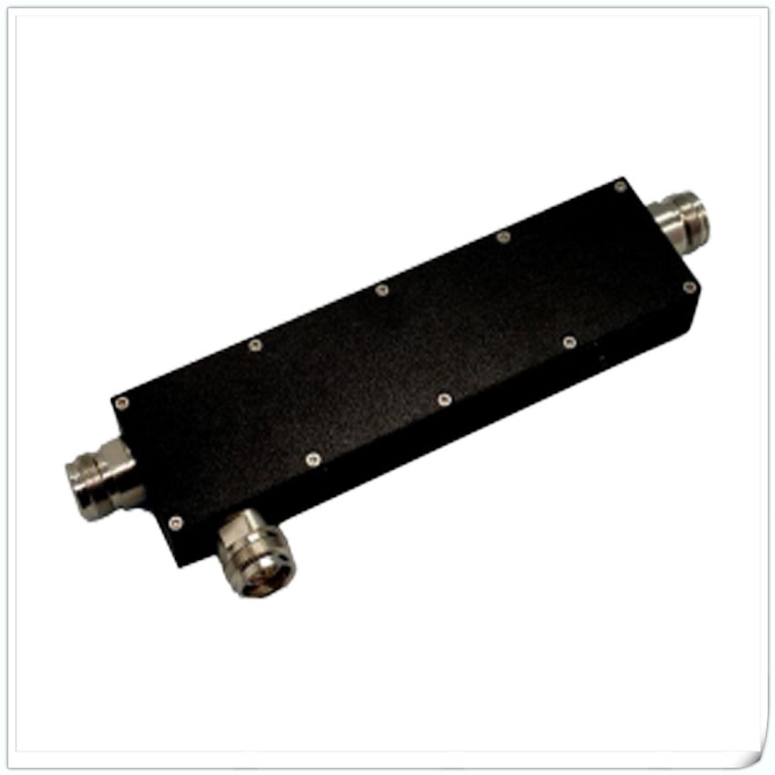
  • RFTYT Low PIM Couplers Combined or Open Circuit

    RFTYT Low PIM Couplers Combined or Open Circuit

    Low intermodulation coupler is a device widely used in wireless communication systems to reduce intermodulation distortion in wireless devices. Intermodulation distortion refers to the phenomenon where multiple signals pass through a nonlinear system at the same time, resulting in the appearance of non existing frequency components that interfere with other frequency components, leading to a decrease in wireless system performance.

    In wireless communication systems, low intermodulation couplers are usually used to separate the input high-power signal from the output signal to reduce intermodulation distortion.

  • RF Coupler (3dB, 10dB, 20dB, 30dB)

    RF Coupler (3dB, 10dB, 20dB, 30dB)

    A coupler is a commonly used RF microwave device used to proportionally distribute input signals to multiple output ports, with output signals from each port having different amplitudes and phases. It is widely used in wireless communication systems, radar systems, microwave measurement equipment, and other fields.

    Couplers can be divided into two types according to their structure: microstrip and cavity. The interior of the microstrip coupler is mainly composed of a coupling network composed of two microstrip lines, while the interior of the cavity coupler is just composed of two metal strips.