
-

CT-02W-RA0612-1.85J-67G Coaxial Fixed Termination
Model CT-02W-RA0612-1.85J-67G Frequency Range DC~67.0GHz VSWR 1.30 Max Power 2W Impedance 50 Ω Connector Type 1.85-M (J) Dimension Φ6.4×11.9mm Operating Temperature -55 ~ +125°C (See de Power De-rating) Weight 3g ROHS Compliant Yes Use attention Power De-rating P/N Designation -

CT-02W-RA0612-1.85J-67G Coaxial Fixed Termination
Model CT-01W-RA0814-1.0J-110G Frequency Range DC~110.0GHz VSWR 1.50 Max Power 1W Impedance 50 Ω Connector Type 1.0-M (J) Dimension Φ7.5×13.7mm Operating Temperature -55 ~ +125°C (See de Power De-rating) Weight 3g ROHS Compliant Yes Use attention Power De-rating P/N Designation -

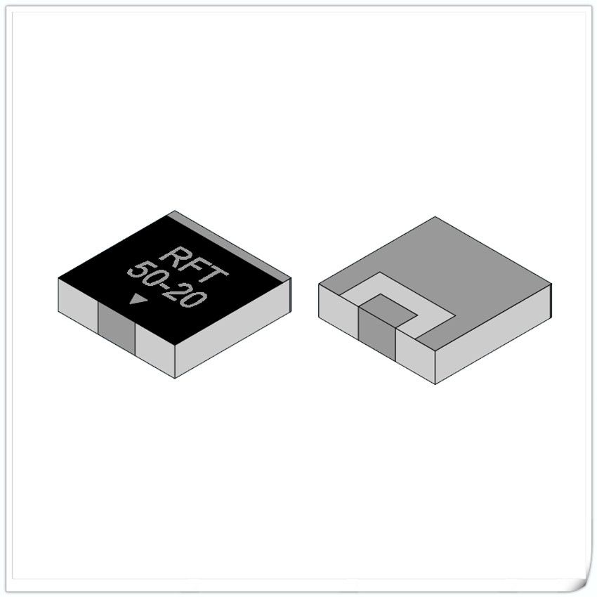
RFT50-20TM7750(R,L) Flanged Termination
Model RFT50-20TM7750(R,L) Frequency Range DC~4.0GHz Power 20 W Resistance Range 50 Ω Resistance Tolerance ±5% VSWR 1.20 max Temperature Coefficient <150ppm/℃ Substrate Material BeO Cap Material Al2O3 Flange Nickel-plated copper Lead 99.99% Sterling silver Resistance Technology Thick Film Operating Temperature -55 to +155°C (See de Power De-rating) Typical Performance: Installation method Power De-rating P/N Designation Matters needing attention ... -

RFT50-10TM7750(R,L) Flanged Termination
Model RFT50-10TM7750(R,L) Frequency Range DC~4.0GHz Power 10 W Resistance Range 50 Ω Resistance tolerance ±5% VSWR 1.20 max Temperature coefficient <150ppm/℃ Substrate material BeO Cap material Al2O3 Flange Nickel-plated copper Lead 99.99% Sterling silver Resistance technology Thick Film Operating Temperature -55 to +155°C (See de Power De-rating) Typical Performance: Installation method Power De-rating P/N Designation Matters needing attention ... -

RFT50A-05TM1104 Flanged Termination
Model RFT50A-05TM1104 Frequency Range DC~6.0GHz Power 5 W Resistance Range 50 Ω Resistance tolerance ±5% VSWR 1.20 max Temperature coefficient <150ppm/℃ Substrate material Al2O3 Cap material Al2O3 Flange Nickel-plated copper Lead 99.99% Sterling silver Resistance technology Thick Film Operating Temperature -55 to +155°C (See de Power De-rating) Typical Performance: Installation method Power De-rating P/N Designation Matters needing attention ■ A... -

RFT50N-05TJ1225 DC~12.0GHz Leaded Termination
Model RFT50A-05TM0404 Frequency Range DC~6.0GHz Power 5 W Resistance Range 50 Ω Resistance tolerance ±5% VSWR 1.20 max Temperature coefficient <150ppm/℃ Substrate material Al2O3 Cap material Al2O3 Lead 99.99% Sterling silver Resistance technology Thick Film Operating Temperature -55 to +155°C (See de Power De-rating) Typical Performance: Installation method Power De-rating Reflow time and temperature diagram: P/N Designation Matters needing attent... -

RFT50-10CT0404 Chip Termination
Model RFT50-10CT0404 Frequency Range DC~10.0GHz Power 10 W Resistance Range 50 Ω Resistance tolerance ±5% VSWR DC~6.0GHz 1.20MaxDC~10.0GHz 1.30Max Temperature coefficient <150ppm/℃ Substrate material BeO Resistance technology Thick Film Operating Temperature -55 to +155°C (See de Power De-rating) Typical Performance: Installation method Power De-rating Reflow time and temperature diagram: P/N Designation Matters needing attention ■ After the storage p... -
Chip Termination
Chip Termination is a common form of electronic component packaging, commonly used for surface mount of circuit boards. Chip resistors are one type of resistor used to limit current, regulate circuit impedance, and local voltage.Unlike traditional socket resistors, patch terminal resistors do not need to be connected to the circuit board through sockets, but are directly soldered to the surface of the circuit board. This packaging form helps to improve the compactness, performance, and reliability of circuit boards.
-

Coaxial Mismatch Termination
Mismatch Termination also called mismatch load which is a type of coaxial load.It is a standard mismatch load that can absorb a portion of microwave power and reflect another portion, and create a standing wave of a certain size, mainly used for microwave measurement.
-

Leaded Termination
Leaded Termination is a resistor installed at the end of a circuit, which absorbs signals transmitted in the circuit and prevents signal reflection, thereby affecting the transmission quality of the circuit system.Leaded Terminations are also known as SMD single lead terminal resistors. It is installed at the end of the circuit by welding. The main purpose is to absorb signal waves transmitted to the end of the circuit, prevent signal reflection from affecting the circuit, and ensure the transmission quality of the circuit system.


