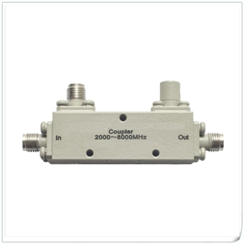
Products
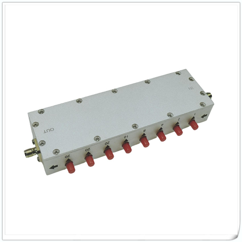
RF Variable Attenuator
Data Sheet
RF Variable Attenuator
Main specs:
A1 type Variable Attenuator
Frequency Range:DC-6.0GHz
Attenuation Step:
min 0-10dB(0.1dB step),
max 0-90dB(10dB step)
Nominal Impedance:50Ω;
Average Power:2W、10W
Peak Power:100W(5uS Pulse width,2% duty cycle)
Connector Type:SMA(FF);N(FF)
Temperature Range:-20~85℃
Dimension:Φ30×62mm
Weight:210 g
ROHS Compliant:Yes

| Model | Freq. Range GHz |
Attenuation & Step |
VSWR (max) |
Insertion Loss dB(max) |
Attenuation Tolerance dB |
Data sheet | |
| RKTXX-1-1-2.5-A1 | DC-2.5 | 0-1dB 0.1dB step |
1.25 | 0.4 | ±0.2 | ||
| RKTXX-1-1-3.0-A1 | DC-3.0 | 1.3 | 0.5 | ±0.2 | |||
| RKTXX-1-1-4.3-A1 | DC-4.3 | 1.35 | 0.75 | ±0.3 | |||
| RKTXX-1-1-6.0-A1 | DC-6.0 | 1.4 | 1 | ±0.4 | |||
| RKTXX-1-10-2.5-A1 | DC-2.5 | 0-10dB 1dB step |
1.25 | 0.4 | ±0.4 | ||
| RKTXX-1-10-3.0-A1 | DC-3.0 | 1.3 | 0.5 | ±0.5 | |||
| RKTXX-1-10-4.3-A1 | DC-4.3 | 1.35 | 0.75 | ±0.5 | |||
| RKTXX-1-10-6.0-A1 | DC-6.0 | 1.4 | 1 | ±0.5 | |||
| RKTXX-1-60-2.5-A1 | DC-2.5 | 0-60dB 10dB step |
1.25 | 0.4 | ±0.5(<40dB) ±3%(≥40dB) |
||
| RKTXX-1-60-3.0-A1 | DC-3.0 | 1.3 | 0.5 | ||||
| RKTXX-1-60-4.3-A1 | DC-4.3 | 1.35 | 0.75 | ||||
| RKTXX-1-60-6.0-A1 | DC-6.0 | 1.4 | 1.0 | ||||
| RKTXX-1-90-2.5-A1 | DC-2.5 | 0-90dB 10dB step |
1.25 | 0.4 | ±0.5(<40dB) ±3%(≥40dB) |
||
| RKTXX-1-90-3.0-A1 | DC-3.0 | 1.3 | 0.5 | ±0.5(<40dB) ±3.5%(≥40dB) |
A2 type Variable Attenuator
Frequency Range:DC-6.0GHz
Attenuation Step:
min 0-10dB(0.1dB step),
max 0-100dB(1dB step)
Nominal Impedance:50Ω;
Average Power:2W、10W
Peak Power:100W(5uS Pulse width,2% duty cycle)
Connector Type:SMA(FF);N(FF)
Temperature Range:-20~85℃
Dimension:Φ30×120mm
Weight:410 g
ROHS Compliant:Yes

| Model | Freq. Range GHz |
Attenuation & Step |
VSWR (max) |
Insertion Loss dB(max) |
Attenuation Tolerance dB |
Data sheet | |
| SMA | N | ||||||
| RKTXX-2-11-2.5-A2 | DC-2.5 | 0-11dB 0.1dB Step |
1.3 | 1.45 | 1.0 | ±0.2<1dB,±0.4≥1dB | |
| RKTXX-2-11-3.0-A2 | DC-3.0 | 1.35 | 1.45 | 1.2 | ±0.3<1dB,±0.5≥1dB | ||
| RKTXX-2-11-4.3-A2 | DC-4.3 | 1.4 | 1.55 | 1.5 | |||
| RKTXX-2-11-6.0-A2 | DC-6.0 | 1.55 | 1.6 | 1.8 | |||
| RKTXX-2-50-2.5-A2 | DC-2.5 | 0-50dB 1dB Step |
1.3 | 1.35 | 1.0 | ±0.5(≤10dB) ±3%(≤50dB) |
|
| RKTXX-2-70-2.5-A2 | DC-2.5 | 0-70dB 1dB Step |
1.3 | 1.45 | 1.0 | ±0.5(≤10dB) ±3%(<70dB) ±3.5%(70dB) |
|
| RKTXX-2-70-3.0-A2 | DC-3.0 | 1.35 | 1.45 | 1.2 | |||
| RKTXX-2-70-4.3-A2 | DC-4.3 | 1.4 | 1.55 | 1.5 | |||
| RKTXX-2-70-6.0-A2 | DC-6.0 | 1.55 | 1.6 | 1.8 | |||
| RKTXX-2-100-2.5-A2 | DC-2.5 | 0-100dB 1dB Step |
1.3 | 1.45 | 1 | ±0.5(≤10dB) ±3%(<70dB) ±3.5%(≥70dB) |
|
| RKTXX-2-100-3.0-A2 | DC-3.0 | 1.35 | 1.45 | 1.2 | |||
A5 type Variable Attenuator
Frequency Range:DC-26.5GHz
Attenuation Step:
min 0-9dB(1dB step),
max 0-99dB(1dB step)
Nominal Impedance:50Ω;
Average Power:2W、10W、25W
Peak Power:
200W(5uS Pulse width,2% duty cycle)
Connector Type:SMA(FF,DC-18GHz);
3.5(FF-26.5GHz)
Temperature Range:0~54℃
Dimension & Weight:
2W (0~9dB) Φ48×96mm 220g
2W/10W(0~90dB) Φ48×108mm 280g
25W Φ48×112.6mm 300g
ROHS Compliant:Yes

| Model | Freq. Range GHz |
Attenuation & Step |
VSWR (max) |
Insertion Loss dB(max) |
Attenuation Tolerance dB |
Data sheet | |
| RKTX2-1-9-8.0-A5 | DC-8.0 | 0-9dB 1dB Step |
1.4 | 0.8 | ±0.6 | PDF |
|
| RKTX2-1-9-12.4-A5 | DC-12.4 | 1.5 | 1 | ±0.8 | |||
| RKTX2-1-9-18.0-A5 | DC-18.0 | 1.6 | 1.2 | ±1.0 | |||
| RKTX2-1-9-26.5-A5 | DC-26.5 | 1.75 | 1.8 | ±1.0 | |||
| RKTX2-1-90-8.0-A5 | DC-8.0 | 0-90dB 10dB Step |
1.4 | 1.0 | ±1.5(10-60dB) ±2.5 or 3.5%(70-90dB) |
||
| RKTX2-1-90-12.4-A5 | DC-12.4 | 1.5 | 1.2 | ||||
| RKTX2-1-90-18.0-A5 | DC-18.0 | 1.6 | 1.5 | ||||
| RKTX10-1-9-8.0-A5 | DC-8.0 | 0-9dB 1dB Step |
1.4 | 0.8 | ±0.6 | ||
| RKTX10-1-9-12.4-A5 | DC-12.4 | 1.5 | 1.0 | ±0.8 | |||
| RKTX10-1-9-18.0-A5 | DC-18.0 | 1.6 | 1.2 | ±1.0 | |||
| RKTX10-1-9-8.0-A5 | DC-26.5 | 1.75 | 1.8 | ±1.0 | |||
| RKTX10-1-90-8.0-A5 | DC-8.0 | 0-90dB 10dB Step |
1.4 | 1.0 | ±1.5(10-60dB) ±2.5 or 3.5%(70-90dB) |
||
| RKTX10-1-90-12.4-A5 | DC-12.4 | 1.5 | 1.2 | ||||
| RKTX10-1-90-18.0-A5 | DC-18.0 | 1.6 | 1.5 | ||||
| RKTX10-1-60-26.5-A5 | DC-26.5 | 0-60dB 10dB Step |
1.75 | 1.8 | ±1.5dB or 4% | ||
| RKTX25-1-70-18.0-A5 | DC-18.0 | 0-70dB 10dB Step |
1.65 | 1 | |||
| RKTX25-1-60-26.5-A5 | DC-26.5 | 0-60dB 10dB Step |
1.8 | 1.8 |
A6 type Variable Attenuator
Frequency Range:DC-26.5GHz
Attenuation Step:
min 0-9dB(1dB step),
max 0-99dB(1dB step)
Nominal Impedance:50Ω;
Average Power:2W、5W
Peak Power:
200W(5uS Pulse width,2% duty cycle)
Connector Type:SMA(FF,DC-18GHz);
3.5(FF-26.5GHz)
Temperature Range:0~54℃
Dimension & Weight:
2W (0~9dB) Φ48×96mm 220g
2W/10W(0~90dB) Φ48×108mm 280g
25W Φ48×112.6mm 300g
ROHS Compliant:Yes

| Model | Freq. Range GHz |
Attenuation & Step |
VSWR (max) |
Insertion Loss dB(max) |
Attenuation Tolerance dB |
Data sheet |
| RKTXX-2-69-8.0-A6 | DC-8.0 | 0-69dB 1dB Step |
1.50 | 1.0 | ±0.5dB(0~9dB) ±1.0dB(10~19dB) ±1.5dB(20~49dB) ±2.0dB(50~69dB) |
|
| RKTXX-2-69-12.4-A6 | DC-12.4 | 1.60 | 1.25 | ±0.8dB(0~9dB) ±1.0dB(10~19dB) ±1.5dB(20~49dB) ±2.0dB(50~69dB) |
||
| RKTXX-2-69-18.0-A6 | DC-18.0 | 1.75 | 1.5 | |||
| RKTXX-2-69-26.5-A6 | DC-26.5 | 2.00 | 2.0 | ±1.5dB(0~9dB) ±1.75dB(10~19dB) ±2.0dB(20~49dB) ±2.5dB(50~69dB) |
||
| RKTXX-2-99-8.0-A6 | DC-8.0 | 0-99dB 1dB Step |
1.50 | 1.0 | ±0.5dB(0~9dB) ±1.0dB(10~19dB) ±1.5dB(20~49dB) ±2.0dB(50~69dB) ±2.5 or 3.5%(70-99dB) |
|
| RKTXX-2-99-12.4-A6 | DC-12.4 | 1.60 | 1.25 | ±0.8dB(0~9dB) ±1.0dB(10~19dB) ±1.5dB(20~49dB) ±2.0dB(50~69dB) ±2.5 or 3.5%(70-99dB) |
||
| RKTXX-2-99-18.0-A6 | DC-18.0 | 1.75 | 1.5 |
Overview
An adjustable attenuator is an electronic device used to control signal strength, which can reduce or increase the power level of a signal as needed.
It is commonly used in wireless communication systems, laboratory measurements, audio equipment, and other electronic fields.
The main function of an adjustable attenuator is to change the power of a signal by adjusting the amount of attenuation it passes through.
It can reduce the power of the input signal to the required value to adapt to different application scenarios.
Meanwhile, adjustable attenuators can also provide good signal matching performance, ensuring accurate and stable frequency response and waveform of the output signal.
In practical applications, adjustable attenuators can be controlled through manual knobs, potentiometers, switches, and other means, or remotely controlled through digital interfaces or wireless communication.
This allows users to adjust the signal strength in real-time as needed to meet different needs.
It should be noted that adjustable attenuators may introduce a certain degree of insertion loss and reflection loss while reducing signal power.
Therefore, when selecting and using adjustable attenuators, it is necessary to comprehensively consider factors such as attenuation range, insertion loss, reflection loss, operating frequency range, and control accuracy.
Summary: Adjustable attenuator is an important electronic device used to control signal strength. It changes the power level of the signal by adjusting the attenuation of the signal to meet different application requirements. Adjustable attenuators have broad application prospects in wireless communication, measurement, and audio fields, and play a key role in the performance and stability of electronic systems.
In practical applications, adjustable attenuators can be controlled through manual knobs, potentiometers, switches, and other means, and can also be remotely controlled through digital interfaces or wireless communication. This allows users to adjust the signal strength in real-time as needed to meet different needs.
It should be noted that adjustable attenuators may introduce a certain degree of insertion loss and reflection loss while reducing signal power. Therefore, when selecting and using adjustable attenuators, it is necessary to comprehensively consider factors such as attenuation range, insertion loss, reflection loss, operating frequency range, and control accuracy.
Summary: Adjustable attenuator is an important electronic device used to control signal strength. It changes the power level of the signal by adjusting its attenuation to meet different application requirements. Adjustable attenuators have broad application prospects in fields such as wireless communication, measurement, and audio, and play a crucial role in the performance and stability of electronic systems.


