
Products


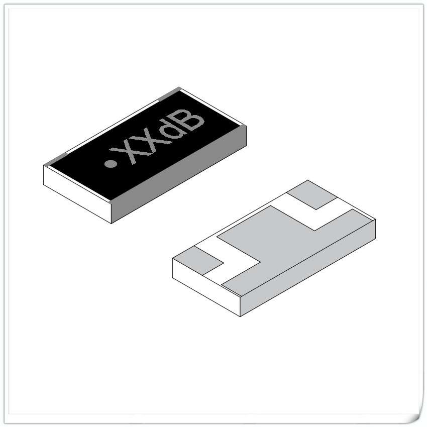
Microstrip Circulator
Data Sheet
| RFTYT Microstrip Circulator Specification | |||||||||
| Model | Frequency range
(GHz) |
Maximum bandwidth | Insert loss
(dB)(Max) |
Isolation
(dB) (Min) |
VSWR
(Max) |
Operation temperature
(℃) |
Peak power (W),
Duty cycle 25% |
Size
(mm) |
Specification |
| MH1515-10 | 2.0~6.0 | Full | 1.3(1.5) | 11(10) | 1.7(1.8) | -55~+85 | 50 | 15.0*15.0*3.5 | |
| MH1515-09 | 2.6-6.2 | Full | 0.8 | 14 | 1.45 | -55~+85 | 40W CW | 15.0*15.0*0.9 | |
| MH1313-10 | 2.7~6.2 | Full | 1.0(1.2) | 15(1.3) | 1.5(1.6) | -55~+85 | 50 | 13.0*13.0*3.5 | |
| MH1212-10 | 2.7~8.0 | 66% | 0.8 | 14 | 1.5 | -55~+85 | 50 | 12.0*12.0*3.5 | |
| MH0909-10 | 5.0~7.0 | 18% | 0.4 | 20 | 1.2 | -55~+85 | 50 | 9.0*9.0*3.5 | |
| MH0707-10 | 5.0~13.0 | Full | 1.0(1.2) | 13(11) | 1.6(1.7) | -55~+85 | 50 | 7.0*7.0*3.5 | |
| MH0606-07 | 7.0~13.0 | 20% | 0.7(0.8) | 16(15) | 1.4(1.45) | -55~+85 | 20 | 6.0*6.0*3.0 | |
| MH0505-08 | 8.0-11.0 | Full | 0.5 | 17.5 | 1.3 | -45~+85 | 10W CW | 5.0*5.0*3.5 | |
| MH0505-08 | 8.0-11.0 | Full | 0.6 | 17 | 1.35 | -40~+85 | 10W CW | 5.0*5.0*3.5 | |
| MH0606-07 | 8.0-11.0 | Full | 0.7 | 16 | 1.4 | -30~+75 | 15W CW | 6.0*6.0*3.2 | |
| MH0606-07 | 8.0-12.0 | Full | 0.6 | 15 | 1.4 | -55~+85 | 40 | 6.0*6.0*3.0 | |
| MH0505-07 | 11.0~18.0 | 20% | 0.5 | 20 | 1.3 | -55~+85 | 20 | 5.0*5.0*3.0 | |
| MH0404-07 | 12.0~25.0 | 40% | 0.6 | 20 | 1.3 | -55~+85 | 10 | 4.0*4.0*3.0 | |
| MH0505-07 | 15.0-17.0 | Full | 0.4 | 20 | 1.25 | -45~+75 | 10W CW | 5.0*5.0*3.0 | |
| MH0606-04 | 17.3-17.48 | Full | 0.7 | 20 | 1.3 | -55~+85 | 2W CW | 9.0*9.0*4.5 | |
| MH0505-07 | 24.5-26.5 | Full | 0.5 | 18 | 1.25 | -55~+85 | 10W CW | 5.0*5.0*3.5 | |
| MH3535-07 | 24.0~41.5 | Full | 1.0 | 18 | 1.4 | -55~+85 | 10 | 3.5*3.5*3.0 | |
| MH0404-00 | 25.0-27.0 | Full | 1.1 | 18 | 1.3 | -55~+85 | 2W CW | 4.0*4.0*2.5 | |
Overview
The advantages of microstrip circulators include small size, light weight, small spatial discontinuity when integrated with microstrip circuits, and high connection reliability. Its relative disadvantages are low power capacity and poor resistance to electromagnetic interference.
Principles for selecting microstrip circulators:
1. When decoupling and matching between circuits, microstrip circulators can be selected.
2. Select the corresponding product model of the microstrip Circulator based on the frequency range, installation size, and transmission direction used.
3. When the operating frequencies of both sizes of microstrip circulators can meet the usage requirements, products with larger volumes generally have higher power capacity.
Circuit connection of microstrip circulator:
The connection can be made using manual soldering with copper strips or gold wire bonding.
1. When purchasing copper strips for manual welding interconnection, the copper strips should be made into an Ω shape, and the solder should not soak into the forming area of the copper strip. Before welding, the surface temperature of the Circulator should be maintained between 60 and 100 ° C.
2. When using gold wire bonding interconnection, the width of the gold strip should be smaller than the width of the microstrip circuit, and composite bonding is not allowed.
RF Microstrip Circulator is a three port microwave device used in wireless communication systems, also known as a ringer or circulator. It has the characteristic of transmitting microwave signals from one port to the other two ports, and has non reciprocity, meaning that signals can only be transmitted in one direction. This device has a wide range of applications in wireless communication systems, such as in transceivers for signal routing and protecting amplifiers from reverse power effects.
The RF Microstrip Circulator mainly consists of three parts: central junction, input port, and output port. A central junction is a conductor with a high resistance value that connects the input and output ports together. Around the central junction are three microwave transmission lines, namely input line, output line, and isolation line. These transmission lines are a form of microstrip line, with electric and magnetic fields distributed on a plane.
The working principle of the RF Microstrip Circulator is based on the characteristics of microwave transmission lines. When a microwave signal enters from the input port, it first transmits along the input line to the central junction. At the central junction, the signal is divided into two paths, one is transmitted along the output line to the output port, and the other is transmitted along the isolation line. Due to the characteristics of microwave transmission lines, these two signals will not interfere with each other during transmission.
The main performance indicators of the RF Microstrip Circulator include frequency range, insertion loss, isolation, voltage standing wave ratio, etc. The frequency range refers to the frequency range within which the device can operate normally, insertion loss refers to the loss of signal transmission from the input port to the output port, isolation degree refers to the degree of signal isolation between different ports, and voltage standing wave ratio refers to the size of the input signal reflection coefficient.
When designing and applying RF Microstrip Circulator, the following factors need to be considered:
Frequency range: It is necessary to select the appropriate frequency range of devices according to the application scenario.
Insertion loss: It is necessary to select devices with low insertion loss to reduce the loss of signal transmission.
Isolation degree: It is necessary to select devices with high isolation degree to reduce interference between different ports.
Voltage standing wave ratio: It is necessary to select devices with low voltage standing wave ratio to reduce the impact of input signal reflection on system performance.
Mechanical performance: It is necessary to consider the mechanical performance of the device, such as size, weight, mechanical strength, etc., to adapt to different application scenarios.