Products
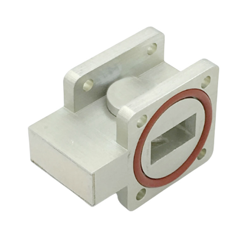
RFTYT 3 Way Power Divider
Data Sheet
| Way | Freq.Range | IL. max(dB) |
VSWR max |
Isolation min(dB) |
Input Power (W) |
Connector Type | Model |
| 3 way | 134-174MHz | 1.0 | 1.35 | 18 | 50 | N-F | PD03-F1610-N/134-174MHz |
| 3 way | 134-3700MHz | 3.6 | 1.50 | 18.0 | 20 | N-F | PD03-F7021-N/134-3700MHz |
| 3 way | 136-174 MHz | 0.4 | 1.30 | 20.0 | 50 | N-F | PD03-F1271-N/136-174MHz |
| 3 way | 300-500MHz | 0.6 | 1.35 | 20.0 | 50 | N-F | PD03-F1271-N/300-500MHz |
| 3 way | 300-500MHz | 0.5 | 1.30 | 18.0 | 50 | N-F | PD03-F1071-N/300-500MHz |
| 3 way | 400-470MHz | 0.5 | 1.30 | 20.0 | 50 | N-F | PD03-F1071-N/400-470MHz |
| 3 way | 698-2700MHz | 0.6 | 1.30 | 20.0 | 50 | N-F | PD03-F1271-N/698-2700MHz |
| 3 way | 698-2700MHz | 0.6 | 1.30 | 20.0 | 50 | SMA-F | PD03-F1271-S/698-2700MHz |
| 3 way | 698-3800MHz | 1.2 | 1.30 | 20.0 | 50 | SMA-F | PD03-F7212-S/698-3800MHz |
| 3 way | 698-3800MHz | 1.2 | 1.30 | 20.0 | 50 | N-F | PD03-F1013-N/698-3800MHz |
| 3 way | 698-4000MHz | 1.2 | 1.30 | 20.0 | 50 | 4.3-10-F | PD03-F8613-M/698-4000MHz |
| 3 way | 698-6000MHz | 2.8 | 1.45 | 18.0 | 50 | SMA-F | PD03-F5013-S/698-6000MHz |
| 3 way | 800-870MHz | 0.8 | 1.35 | 18.0 | 50 | N-F | PD03-F8145-N/800-870MHz |
| 3 way | 800-2700MHz | 0.6 | 1.25 | 20.0 | 50 | N-F | PD03-F1071-N/800-2700MHz |
| 3 way | 800-2700MHz | 0.4 | 1.25 | - | 300 | N-F | PD03-R2260-N/800-2700MHz |
| 3 way | 2.0-8.0GHz | 1.0 | 1.40 | 18.0 | 30 | SMA-F | PD03-F3867-S/2-8GHz |
| 3 way | 2.0-18.0GHz | 1.6 | 1.80 | 16.0 | 30 | SMA-F | PD03-F3970-S/2-18GHz |
| 3 way | 6.0-18.0GHz | 1.5 | 1.80 | 16.0 | 30 | SMA-F | PD03-F3851-S/6-18GHz |
Overview
The 3-way power divider is an important component used in wireless communication systems and RF circuits. It consists of one input port and three output ports, used to allocate input signals to three output ports. It achieves signal separation and power distribution by achieving uniform power distribution and constant phase distribution. It is generally required to have good standing wave performance, high isolation, and good in band flatness.
The main technical indicators of a 3-way power divider are frequency range, power withstand, allocation loss, insertion loss between input and output, isolation between ports, and standing wave ratio of each port.
3-way power splitters are widely used in wireless communication systems and RF circuits. It is often used in fields such as base station systems, antenna arrays, and RF front-end modules.
The 3-way power divider is a common RF device, and its main characteristics and advantages include:
Uniform distribution: The 3-channel power divider can evenly distribute input signals to three output ports, achieving average signal distribution. This is very useful for applications that require simultaneous acquisition or transmission of multiple identical signals, such as antenna array systems.
Broadband: 3-channel power splitters typically have a wide frequency range and can cover a wide frequency range. This makes them suitable for different RF applications, including communication systems, radar systems, measurement equipment, etc.
Low loss: A good power divider design can achieve lower insertion loss. Low loss is very important, especially for high-frequency signal transmission and reception systems, as it can improve signal transmission efficiency and reception sensitivity.
High isolation: Isolation refers to the degree of signal interference between the output ports of the power divider. A 3-way power divider typically provides high isolation, ensuring minimal interference between signals from different output ports, thereby maintaining good signal quality.
Small size: The 3 ways power divider typically adopt miniaturized packaging and structural design, with smaller size and volume. This allows them to be easily integrated into various RF systems, saving space and improving overall system performance.
Customers can choose the appropriate frequency and power divider according to specific application requirements, or directly contact our sales personnel for detailed understanding and purchase.


