Products
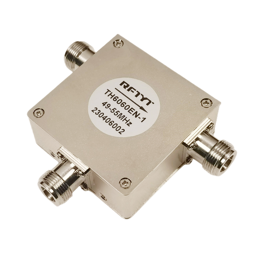
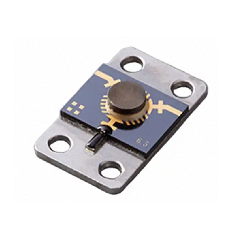
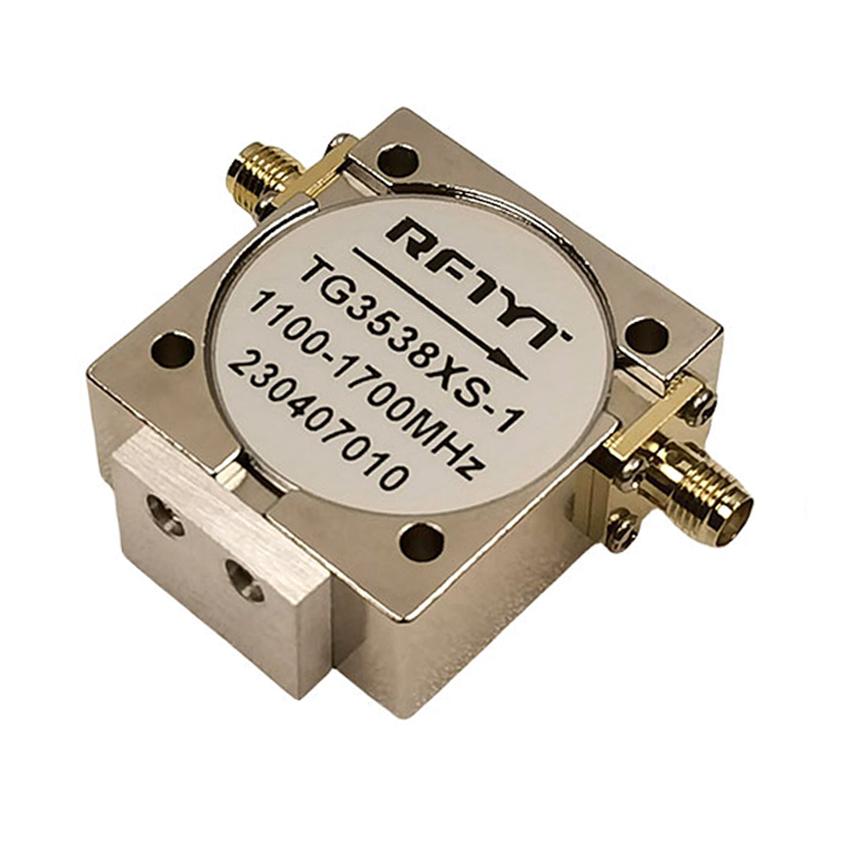
Coaxial Circulator
Data Sheet
| RFTYT 30MHz-18.0GHz RF Coaxial Circulator | |||||||||
| Model | Freq.Range | BW Max. | IL.(dB) | Isolation (dB) | VSWR | Forward Power (W) | Dimension WxLxHmm | SMA Type | N Type |
| TH6466H | 30-40MHz | 5% | 2.00 | 18.0 | 1.30 | 100 | 60.0*60.0*25.5 | ||
| TH6060E | 40-400 MHz | 50% | 0.80 | 18.0 | 1.30 | 100 | 60.0*60.0*25.5 | ||
| TH5258E | 160-330 MHz | 20% | 0.40 | 20.0 | 1.25 | 500 | 52.0*57.5*22.0 | ||
| TH4550X | 250-1400 MHz | 40% | 0.30 | 23.0 | 1.20 | 400 | 45.0*50.0*25.0 | ||
| TH4149A | 300-1000MHz | 50% | 0.40 | 16.0 | 1.40 | 30 | 41.0*49.0*20.0 | / | |
| TH3538X | 300-1850 MHz | 30% | 0.30 | 23.0 | 1.20 | 300 | 35.0*38.0*15.0 | ||
| TH3033X | 700-3000 MHz | 25% | 0.30 | 23.0 | 1.20 | 300 | 32.0*32.0*15.0 | / | |
| TH3232X | 700-3000 MHz | 25% | 0.30 | 23.0 | 1.20 | 300 | 30.0*33.0*15.0 | / | |
| TH2528X | 700-5000 MHz | 25% | 0.30 | 23.0 | 1.20 | 200 | 25.4*28.5*15.0 | ||
| TH6466K | 950-2000 MHz | Full | 0.70 | 17.0 | 1.40 | 150 | 64.0*66.0*26.0 | ||
| TH2025X | 1300-6000 MHz | 20% | 0.25 | 25.0 | 1.15 | 150 | 20.0*25.4*15.0 | / | |
| TH5050A | 1.5-3.0 GHz | Full | 0.70 | 18.0 | 1.30 | 150 | 50.8*49.5*19.0 | ||
| TH4040A | 1.7-3.5 GHz | Full | 0.70 | 17.0 | 1.35 | 150 | 40.0*40.0*20.0 | ||
| TH3234A | 2.0-4.0 GHz | Full | 0.40 | 18.0 | 1.30 | 150 | 32.0*34.0*21.0 | ||
| TH3234B | 2.0-4.0 GHz | Full | 0.40 | 18.0 | 1.30 | 150 | 32.0*34.0*21.0 | ||
| TH3030B | 2.0-6.0 GHz | Full | 0.85 | 12.0 | 1.50 | 50 | 30.5*30.5*15.0 | / | |
| TH2528C | 3.0-6.0 GHz | Full | 0.50 | 20.0 | 1.25 | 150 | 25.4*28.0*14.0 | ||
| TH2123B | 4.0-8.0 GHz | Full | 0.60 | 18.0 | 1.30 | 60 | 21.0*22.5*15.0 | ||
| TH1620B | 6.0-18.0 GHz | Full | 1.50 | 9.5 | 2.00 | 30 | 16.0*21.5*14.0 | / | |
| TH1319C | 6.0-12.0 GHz | Full | 0.60 | 15.0 | 1.45 | 30 | 13.0*19.0*12.7 | / | |
Overview
The coaxial circulator is a branch transmission system with non reciprocal characteristics. The ferrite RF circulator is composed of a Y-shaped center structure, which is composed of three branch lines symmetrically distributed at an angle of 120 ° to each other. When a magnetic field is applied to the circulator, the ferrite is magnetized. When the signal is input from terminal 1, a magnetic field is excited on the ferrite junction, and the signal is transmitted to output from terminal 2. Similarly, the signal input from terminal 2 is transmitted to terminal 3, and the signal input from terminal 3 is transmitted to terminal 1. Due to its function of signal cycle transmission, it is called an RF circulator.
Typical use of a circulator: a common antenna for transmitting and receiving signals.
The working principle of a coaxial circulator is based on the asymmetric transmission of a magnetic field. When a signal enters a coaxial transmission line from one direction, magnetic materials guide the signal to the other direction and isolate it. Due to the fact that magnetic materials only act on signals in specific directions, coaxial circulators can achieve unidirectional transmission and isolation of signals. Meanwhile, due to the special characteristics of the inner and outer conductors of coaxial transmission lines and the influence of magnetic materials, coaxial circulators can achieve low insertion loss and high isolation. Coaxial circulators have several advantages. Firstly, it has low insertion loss, which reduces signal attenuation and energy loss. Secondly, the coaxial circulator has high isolation, which can effectively isolate input and output signals and avoid mutual interference. In addition, coaxial circulators have broadband characteristics and can support a wide range of frequency and bandwidth requirements. In addition, the coaxial circulator is resistant to high power and suitable for high-power applications. Coaxial circulators are widely used in various RF and microwave systems. In communication systems, coaxial circulators are typically used to isolate signals between different devices to prevent echoes and interference. In radar and antenna systems, coaxial circulators are used to control the direction of signals and isolate input and output signals to improve system performance. In addition, coaxial circulators can also be used for signal measurement and testing, providing accurate and reliable signal transmission. When selecting and using coaxial circulators, it is necessary to consider some important parameters. This includes the operating frequency range, which requires selecting an appropriate frequency range; Isolation to ensure good isolation effect; Insertion loss, try to choose low loss devices; Power processing capability to meet the power requirements of the system. According to specific application requirements, different models and specifications of coaxial circulators can be selected.
RF coaxial ring devices belong to non reciprocal passive devices. The frequency range of RFTYT's RF coaxial ringer is from 30MHz to 31GHz, with specific characteristics such as low insertion loss, high isolation, and low standing wave. RF coaxial ringers belong to three port devices, and their connectors are usually SMA, N, 2.92, L29, or DIN types. RFTYT company specializes in the research and development, production, and sales of RF ring-shaped devices, with a history of 17 years. There are multiple models to choose from, and large-scale customization can also be carried out according to customer needs. If the product you want is not listed in the table above, please contact our sales personnel.


