
Products

Flanged Attenuator
Overview
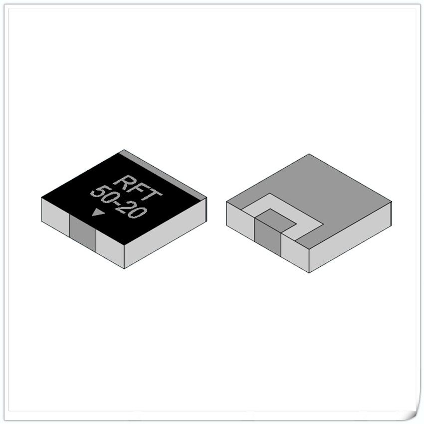
The basic principle of a flanged mount attenuator is to consume some of the energy of the input signal, causing it to generate a lower intensity signal at the output end. This can achieve accurate control and adaptation of signals in the circuit to meet specific requirements. Flanged mount attenuators can adjust a wide range of attenuation values, usually between a few decibels to tens of decibels, to meet the signal attenuation needs in different scenarios.
Flanged mount attenuators have a wide range of applications in wireless communication systems. For example, in the field of mobile communication, Flanged mount attenuators are used to adjust transmission power or reception sensitivity to ensure signal adaptability at different distances and environmental conditions. In RF circuit design, Flanged mount attenuators can be used to balance the strength of input and output signals, avoiding high or low signal interference. In addition, Flanged mount attenuators are widely used in testing and measurement fields, such as calibrating instruments or adjusting signal levels.
It should be noted that when using flanged mount attenuators, it is necessary to select them based on specific application scenarios, and pay attention to their operating frequency range, maximum power consumption, and linearity parameters to ensure their normal operation and long-term stability.
Data Sheet
| Power | Frequency Range GHz |
Dimension(mm) | Attenuation Value dB |
Substrate Material | Configuration | Data Sheet (PDF) |
|||||||||
| A | B | C | D | E | H | G | L | W | Φ | ||||||
| 5W | DC-3.0 | 13.0 | 4.0 | 9.0 | 4.0 | 0.8 | 1.8 | 2.8 | 3.0 | 1.0 | 2.0 | 01-10、15、17、20、25、30 | Al2O3 | FIG1 | RFTXXA-05AM1304-3G |
| 11.0 | 4.0 | 7.0 | 4.0 | 0.8 | 1.8 | 2.8 | 3.0 | 1.0 | 2.0 | 01-10、15、17、20、25、30 | Al2O3 | FIG1 | RFTXXA-05AM1104-3G | ||
| 9.0 | 4.0 | 7.0 | 4.0 | 0.8 | 1.8 | 2.8 | 3.0 | 1.0 | 2.0 | 01-10、15、17、20、25、30 | Al2O3 | FIG3 | RFTXXA-05AM0904-3G | ||
| 10W | DC-4.0 | 7.7 | 5.0 | 5.1 | 2.5 | 1.5 | 2.5 | 3.5 | 4.0 | 1.0 | 3.1 | 0.5、01-04、07、10、11 | BeO | FIG4 | RFTXX-10AM7705B-4G |
| 30W | DC-6.0 | 20.0 | 6.0 | 14.0 | 6.0 | 1.5 | 2.5 | 3.3 | 5.0 | 1.0 | 3.2 | 01-10、15、20、25、30 | BeO | FIG1 | RFTXX-30AM2006-6G |
| 16.0 | 6.0 | 13.0 | 6.0 | 1.0 | 2.0 | 2.8 | 5.0 | 1.0 | 2.1 | 01-10、15、20、25、30 | BeO | FIG1 | RFTXX-30AM1606-6G | ||
| 13.0 | 6.0 | 10.0 | 6.0 | 1.5 | 2.5 | 3.3 | 5.0 | 1.0 | 3.2 | 01-10、15、20、25、30 | BeO | FIG3 | RFTXX-30AM1306-6G | ||
| 60W | DC-3.0 | 16.6 | 6.35 | 12.0 | 6.35 | 1.5 | 2.5 | 3.3 | 5.0 | 1.4 | 2.5 | 01-10、16、20 | BeO | FIG2 | RFTXX-60AM1663B-3G |
| 13.0 | 6.35 | 10.0 | 6.35 | 1.5 | 2.5 | 3.3 | 5.0 | 1.4 | 3.2 | 01-10、16、20 | BeO | FIG4 | RFTXX-60AM1363B-3G | ||
| 13.0 | 6.35 | 10.0 | 6.35 | 1.5 | 2.5 | 3.3 | 5.0 | 1.4 | 3.2 | 01-10、16、20 | BeO | FIG5 | RFTXX-60AM1363C-3G | ||
| DC-6.0 | 20.0 | 6.0 | 14.0 | 6.0 | 1.5 | 2.5 | 3.3 | 5.0 | 1.0 | 3.2 | 01-10、15、20、25、30 | BeO | FIG1 | RFTXX-60AM2006-6G | |
| 16.0 | 6.0 | 13.0 | 6.0 | 1.0 | 2.0 | 2.8 | 5.0 | 1.0 | 2.1 | 01-10、15、20、25、30 | BeO | FIG1 | RFTXX-60AM1606-6G | ||
| 13.0 | 6.0 | 10.0 | 6.0 | 1.5 | 2.5 | 3.3 | 5.0 | 1.0 | 3.2 | 01-10、15、20、25、30 | BeO | FIG3 | RFTXX-60AM1306-6G | ||
| 16.6 | 6.35 | 12.0 | 6.35 | 1.5 | 2.5 | 3.3 | 5.0 | 1.0 | 2.5 | 20 | ALN | FIG1 | RFT20N-60AM1663-6G | ||
| 100W | DC-3.0 | 20.0 | 6.0 | 14.0 | 8.9 | 1.5 | 2.5 | 3.0 | 5.0 | 1.0 | 3.2 | 13、20、30 | ALN | FIG1 | RFTXXN-100AJ2006-3G |
| DC-6.0 | 20.0 | 6.0 | 14.0 | 9.0 | 1.5 | 2.5 | 3.3 | 5.0 | 1.0 | 3.2 | 01-10、15、20、25、30 | BeO | FIG1 | RFTXX-100AM2006-6G | |
| 150W | DC-3.0 | 24.8 | 9.5 | 18.4 | 9.5 | 3.0 | 4.3 | 5.5 | 5.0 | 1.0 | 3.6 | 03、04(AlN) /12、30 (BeO) | ALN/BeO | FIG2 | RFTXXN-150AM2595B-3G RFTXX-150AM2595B-3G |
| 24.8 | 10.0 | 18.4 | 10.0 | 3.0 | 4.5 | 5.5 | 6.0 | 2.4 | 3.5 | 25、26、27、30 | BeO | FIG1 | RFTXX-150AM2510-3G | ||
| 23.0 | 10.0 | 17.0 | 10.0 | 1.5 | 3.0 | 4.0 | 6.0 | 2.4 | 3.2 | 25、26、27、30 | BeO | FIG1 | RFTXX-150AM2310-3G | ||
| DC-6.0 | 24.8 | 10.0 | 18.4 | 10.0 | 3.0 | 4.5 | 5.5 | 6.0 | 2.4 | 3.5 | 01-10、15、17、19、20、21、23、24 | BeO | FIG1 | RFTXX-150AM2510-6G | |
| 23.0 | 10.0 | 17.0 | 10.0 | 1.5 | 3.0 | 4.0 | 6.0 | 2.4 | 3.2 | 01-10、15、17、19、20、21、23、24 | BeO | FIG1 | RFTXX-150AM2310-6G | ||
| 250W | DC-1.5 | 24.8 | 10.0 | 18.4 | 10.0 | 3.0 | 4.5 | 5.5 | 6.0 | 2.4 | 3.5 | 01-03、20、30 | BeO | FIG1 | RFTXX-250AM2510-1.5G |
| 23.0 | 10.0 | 17.0 | 10.0 | 1.5 | 3.0 | 4.0 | 6.0 | 2.4 | 3.2 | 01-03、20、30 | BeO | FIG1 | RFTXX-250AM2310-1.5G | ||
| 300W | DC-1.5 | 24.8 | 10.0 | 18.4 | 10.0 | 3.0 | 4.5 | 5.5 | 6.0 | 2.4 | 3.5 | 01-03、30 | BeO | FIG1 | RFTXX-300AM2510-1.5G |